Epson 2070 Service Manual - Page 67
V Line Constant Voltage Control Circuit
 |
UPC - 010343812277
View all Epson 2070 manuals
Add to My Manuals
Save this manual to your list of manuals |
Page 67 highlights
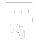
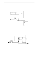
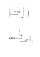
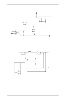
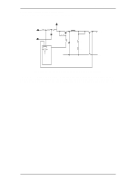
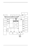
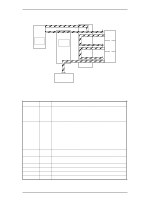
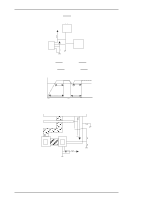
LQ-2070 Service Manual 3. +35 V Constant Voltage Control Circuit The +35 V constant voltage control circuit is illustrated below. Operating Principles 11 C15 Q1 C13 R11 10+ R20 R21 Q2 R15 Q3 R19 R16 R13 R14 C12 + IC1 9+ 81 72 R56 D81 R57 +35V Line ZD51 ZD81 ZD82 ZD83 ZD84 ZD85 GND Line Figure 2-25 +35 V Line Constant Voltage Control Circuit The constant voltage control circuit operates to keep the 35 V line at 35 V ± 6 %. When the voltage between ZD51 and ZD85 becomes 32.7 V ± 2.75 %, PC1 turns on, and then Q2 also turns on. Consequently, switching FET Q1 shuts off. When the voltage between ZD51 and ZD85 becomes less than 32.7 ± 2.75 V, PC1 turns off, and then Q2 also turns off. Consequently, switching FET Q1 operates again. Repeating the above operation keeps the +35 V line at 35 V ± 6%. 4. +35V Line Overload Detection Circuit The +35 V line voltage drop protection circuit is shown in the figure below. +35V Line ZD51 ZD81 ZD82 ZD83 ZD84 ZD85 +5V Line PC1 R56 D81 81 R57 Q31 72 GND Line R83 R20 R84 R86 5 8+ 64 - 7 R87 PWDN GND Figure 2-26 +35 V Line Overload Detection Circuit When the +35 V line is overloaded, it means that constant voltage control is not being maintained. In this condition, the forward current of PC1 drops to 0 A. Consequently, voltage Vf between PC1 and D81 also drops. On this circuit, when the Vf voltage drops below 1.3 V (+35 V line: 33.1 V), IC528 detects the overload and outputs the PWDN signal (+5 V: HIGH active) to port 20 of the CPU. When the CPU receives this PWDN signal, printing stops. When the +35 V line becomes normal again, the voltage between PC1 and D81 also becomes normal. When the Vf voltage goes above 1.6 V (+35 V line: 33.4 V), the PWDN signal is removed. Rev.A 2-19
-
 1
1 -
2
-
3
-
4
-
5
-
6
-
7
-
8
-
9
-
10
-
11
-
12
-
13
-
14
-
15
-
16
-
17
-
18
-
19
-
20
-
21
-
22
-
23
-
24
-
25
-
26
-
27
-
28
-
29
-
30
-
31
-
32
-
33
-
34
-
35
-
36
-
37
-
38
-
39
-
40
-
41
-
42
-
43
-
44
-
45
-
46
-
47
-
48
-
49
-
50
-
51
-
52
-
53
-
54
-
55
-
56
-
57
-
58
-
59
-
60
-
61
-
 62
62 -
 63
63 -
 64
64 -
 65
65 -
 66
66 -
 67
67 -
 68
68 -
 69
69 -
 70
70 -
 71
71 -
 72
72 -
73
-
74
-
75
-
76
-
77
-
78
-
79
-
80
-
81
-
82
-
83
-
84
-
85
-
86
-
87
-
88
-
89
-
90
-
91
-
92
-
93
-
94
-
95
-
96
-
97
-
98
-
99
-
100
-
101
-
102
-
103
-
104
-
105
-
106
-
107
-
108
-
109
-
110
-
111
-
112
-
113
-
114
-
115
-
116
-
117
-
118
-
119
-
120
-
121
-
122
-
123
-
124
-
125
-
126
-
127
-
128
-
129
-
130
-
131
-
132
-
133
-
134
-
135
-
136
-
137
-
138
-
139
-
140
-
141
-
142
-
143
-
144
-
145
-
146
-
147
-
148
-
149
-
150
-
151
-
152
-
153
-
154
-
155
-
156
-
157
-
158
-
159
-
160
-
161
-
162
-
163
-
164
-
165
 |
 |
