Epson 2070 Service Manual - Page 93
Removing the PG Sensor Assembly
 |
UPC - 010343812277
View all Epson 2070 manuals
Add to My Manuals
Save this manual to your list of manuals |
Page 93 highlights
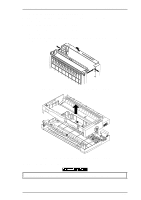
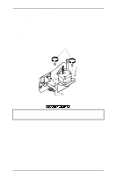
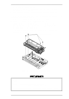
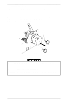
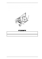
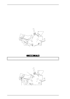
LQ-2070 Service Manual Disassembly and Assembly 3.2.9.2 Removing the PG Sensor Assembly 1. Remove the rear/front edge guide assembly, front cover, paper eject assembly, rear/front tractor unit, and printer cover (see Section 3.2.1). 2. Remove the panel board (see Section 3.2.2) and upper housing assemblies (see Section 3.2.7). 3. Remove the printer mechanism (see Section 3.2.9 ). 4. Remove the hexagon nut (standard, M4) securing the PG sensor assembly to the right frame assembly. Hexagon Nut(Standard,M4) Figure 3-18 Removing the PG Sensor Assembly Assembly Notes The tightening torque for the hexagon nut (standard, M4) = 1.18 ~ 1.37 Nm (12 ~ 14 Kg f - cm) When securing the shaft, push the front CR guide shaft to the bottom of the cutout. Rev.A 3-15
-
 1
1 -
2
-
3
-
4
-
5
-
6
-
7
-
8
-
9
-
10
-
11
-
12
-
13
-
14
-
15
-
16
-
17
-
18
-
19
-
20
-
21
-
22
-
23
-
24
-
25
-
26
-
27
-
28
-
29
-
30
-
31
-
32
-
33
-
34
-
35
-
36
-
37
-
38
-
39
-
40
-
41
-
42
-
43
-
44
-
45
-
46
-
47
-
48
-
49
-
50
-
51
-
52
-
53
-
54
-
55
-
56
-
57
-
58
-
59
-
60
-
61
-
62
-
63
-
64
-
65
-
66
-
67
-
68
-
69
-
70
-
71
-
72
-
73
-
74
-
75
-
76
-
77
-
78
-
79
-
80
-
81
-
82
-
83
-
84
-
85
-
86
-
87
-
 88
88 -
 89
89 -
 90
90 -
 91
91 -
 92
92 -
 93
93 -
 94
94 -
 95
95 -
 96
96 -
 97
97 -
 98
98 -
99
-
100
-
101
-
102
-
103
-
104
-
105
-
106
-
107
-
108
-
109
-
110
-
111
-
112
-
113
-
114
-
115
-
116
-
117
-
118
-
119
-
120
-
121
-
122
-
123
-
124
-
125
-
126
-
127
-
128
-
129
-
130
-
131
-
132
-
133
-
134
-
135
-
136
-
137
-
138
-
139
-
140
-
141
-
142
-
143
-
144
-
145
-
146
-
147
-
148
-
149
-
150
-
151
-
152
-
153
-
154
-
155
-
156
-
157
-
158
-
159
-
160
-
161
-
162
-
163
-
164
-
165
 |
 |
