Epson 2070 Service Manual - Page 102
Removing the C186 MAIN Board Assembly
 |
UPC - 010343812277
View all Epson 2070 manuals
Add to My Manuals
Save this manual to your list of manuals |
Page 102 highlights
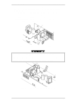
Disassembly and Assembly LQ-2070 Service Manual 3.2.10 Removing the C186 MAIN Board Assembly 1. Remove the rear/front edge guide assembly, front cover, paper eject assembly, rear/front tractor unit, and printer cover (see Section 3.2.1) 2. Remove the panel board (see Section 3.2.2) and upper housing assembly (see Section 3.2.7). 3. Disconnect the following connectors from the C186 MAIN board assembly. CN3 (10-pin , blue) CN6 (2-pin, white) CN9 (15-pin, white FFC) CN12 (2-pin, white) CN16 (2-pin, yellow) CN4 (3-pin, white) CN7 (4-pin, white FFC) CN10 (4-pin, blue) CN13 (2-pin, black) CN5 (3-pin, black) CN8 (17-pin, white FFC) CN11 (5-pin, blue) CN15 (22-pin FFC) f Disconnect the cables for CN10 and CN11 after releasing the connector lock. f Disconnect the cable for CN3 by pushing down the connector lock. 4. Remove the 2 CBS screws ( 3 × 12, F/Zn) securing the upper connector cover. 5. Remove 5 CBB screws (3 × 12, F/Zn) and 1 CBC lamitite screw (3 × 8, F/Zn ) securing the C186 MAIN board assembly to the lower housing assembly. 6. Remove the option I/F cage from the C186 MAIN board by releasing the hooks fixing it to the C186 MAIN board. C186 MAIN Board Assembly Figure 3-35 Removing the C186 Main Board Assembly 7. Remove the C186 MAIN board assembly. Assembly Notes Notice the location of the CBC lamitite screw (3 × 8, F/Zn). Refer to the above figure. Lock CN10 and CN11 by pushing down each connector's lock after inserting the connector cable. The tightening torque for the CBB (3 × 12, F/Zn) screw = 0.78 ~ 0.98 Nm (8 ~ 10 Kg f - cm) The tightening torque for CBB (3 × 8, F/Zn) screw = 0.78 ~ 0.98 Nm (8 ~ 10 Kg f - cm) If you replace the main board, adjust the bidirectional print alignment and run the default setting program. Refer to Chapter 4. 3-24 Rev.A
-
 1
1 -
2
-
3
-
4
-
5
-
6
-
7
-
8
-
9
-
10
-
11
-
12
-
13
-
14
-
15
-
16
-
17
-
18
-
19
-
20
-
21
-
22
-
23
-
24
-
25
-
26
-
27
-
28
-
29
-
30
-
31
-
32
-
33
-
34
-
35
-
36
-
37
-
38
-
39
-
40
-
41
-
42
-
43
-
44
-
45
-
46
-
47
-
48
-
49
-
50
-
51
-
52
-
53
-
54
-
55
-
56
-
57
-
58
-
59
-
60
-
61
-
62
-
63
-
64
-
65
-
66
-
67
-
68
-
69
-
70
-
71
-
72
-
73
-
74
-
75
-
76
-
77
-
78
-
79
-
80
-
81
-
82
-
83
-
84
-
85
-
86
-
87
-
88
-
89
-
90
-
91
-
92
-
93
-
94
-
95
-
96
-
 97
97 -
 98
98 -
 99
99 -
 100
100 -
 101
101 -
 102
102 -
 103
103 -
 104
104 -
 105
105 -
 106
106 -
 107
107 -
108
-
109
-
110
-
111
-
112
-
113
-
114
-
115
-
116
-
117
-
118
-
119
-
120
-
121
-
122
-
123
-
124
-
125
-
126
-
127
-
128
-
129
-
130
-
131
-
132
-
133
-
134
-
135
-
136
-
137
-
138
-
139
-
140
-
141
-
142
-
143
-
144
-
145
-
146
-
147
-
148
-
149
-
150
-
151
-
152
-
153
-
154
-
155
-
156
-
157
-
158
-
159
-
160
-
161
-
162
-
163
-
164
-
165
 |
 |
