Epson 2070 Service Manual - Page 73
CR Motor Driver Circuit, Table 2-8, CR Motor Driver Modes, CR Driver Circuit
 |
UPC - 010343812277
View all Epson 2070 manuals
Add to My Manuals
Save this manual to your list of manuals |
Page 73 highlights
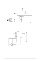
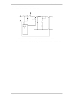
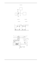
LQ-2070 Service Manual 2.3.4 CR Motor Driver Circuit The CR motor driver circuit is shown below. CPU PG00 1 PG01 2 PG02 3 PG03 4 +5V Address Data Line R72 CRI0 65 R73 64 R74 Gate CRI1 Array CRI2 63 R75 CRI3 62 R76 R71 R67 R68 C29, 30 C31 R69, 70 6 5 IN A 17 IN-A A 16 IN B IN-B -A 3 RFA B 14 RFB -B SLA7024M 9 RSA 10 RSB 4 GND A 15 GNB B Operating Principles CR A CR-A CR B CR-B CRCOM +35V Figure 2-35 CR Driver Circuit The carriage motor driver circuit controls the CR motor, using an open-loop, constant drive arrangement. 2-2 and 1-2 phases excite the motor. A 2-2 phase step is equivalent to a 1-2 phase step doubled. Ports 1 to 4 of the SLA7024M are used to change the excitation phase, depending on the selected print mode. Table 2-8 describes the motor driver modes. Table 2-8 CR Motor Driver Modes Speed Mode Print Speed (CPS) Drive Frequency (PPS) Excitation Phase Applications 36/11 300 7200 1-2 Super Draft 3 275 6600 1-2 Draft 8/3 244 5866 1-2 Super Draft and Copy 2 183 4400 1-2 Super Draft and Power Down 3/2 138 3300 1-2 Draft and Power Down 4400 W1-2 LQ 1 92 1-2 Draft and Copy and Power Down 2/3 61 1464 1-2 LQ and Copy 1/2 46 2200 W1-2 LQ and Power Down 1/3 31 1464 W1-2 LQ and Copy and Power Down 1/4 23 1100 W1-2 Raster Graphics The SLA7024M (IC12) CR motor driver circuit detects and regulates the amount of current flowing in the carriage motor coil. The current flowing through the coil varies, depending on the speed of the CR motor. The CPU sets the amount of current and signals are sent via ports 32 to port 35. The SLA7024M sets the coil current, depending on the CR speed. Rev.A 2-25
-
 1
1 -
2
-
3
-
4
-
5
-
6
-
7
-
8
-
9
-
10
-
11
-
12
-
13
-
14
-
15
-
16
-
17
-
18
-
19
-
20
-
21
-
22
-
23
-
24
-
25
-
26
-
27
-
28
-
29
-
30
-
31
-
32
-
33
-
34
-
35
-
36
-
37
-
38
-
39
-
40
-
41
-
42
-
43
-
44
-
45
-
46
-
47
-
48
-
49
-
50
-
51
-
52
-
53
-
54
-
55
-
56
-
57
-
58
-
59
-
60
-
61
-
62
-
63
-
64
-
65
-
66
-
67
-
 68
68 -
 69
69 -
 70
70 -
 71
71 -
 72
72 -
 73
73 -
 74
74 -
 75
75 -
 76
76 -
 77
77 -
 78
78 -
79
-
80
-
81
-
82
-
83
-
84
-
85
-
86
-
87
-
88
-
89
-
90
-
91
-
92
-
93
-
94
-
95
-
96
-
97
-
98
-
99
-
100
-
101
-
102
-
103
-
104
-
105
-
106
-
107
-
108
-
109
-
110
-
111
-
112
-
113
-
114
-
115
-
116
-
117
-
118
-
119
-
120
-
121
-
122
-
123
-
124
-
125
-
126
-
127
-
128
-
129
-
130
-
131
-
132
-
133
-
134
-
135
-
136
-
137
-
138
-
139
-
140
-
141
-
142
-
143
-
144
-
145
-
146
-
147
-
148
-
149
-
150
-
151
-
152
-
153
-
154
-
155
-
156
-
157
-
158
-
159
-
160
-
161
-
162
-
163
-
164
-
165
 |
 |
