Epson 2070 Service Manual - Page 117
Bidirectional Print Alignment Adjustment, Machine Select Menu
 |
UPC - 010343812277
View all Epson 2070 manuals
Add to My Manuals
Save this manual to your list of manuals |
Page 117 highlights
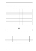
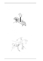
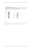
Adjustment LQ-2070 Service Manual 4.2.2 Bidirectional Print Alignment Adjustment This section describes the procedure for adjusting the bidirectional print alignment, required after mechanism repair. This procedure is also necessary if you replace the main board assembly or EEPROM, because the adjusted value is written to the EEPROM on the C186 MAIN board. You can perform the adjustment from the Settings Diskette, using the control panel, or with a remote utility. This section describes the adjustment procedure with the Settings Diskette first, and then describes the adjustment procedure using the control panel. Notes: • When the main board or EEPROM is replaced, reset the Factory Settings first, then perform the bidirectional adjustment. • Do not perform the Bi-d adjustment if the input voltage is fluctuating heavily. 4.2.2.1 Bi-d Print Alignment Adjustment using the Settings Diskette 1. Insert the Settings Diskette into Drive A of the PC and turn the power on. 2. Type GWBASIC and press ENTER. 3. Load and run the J10A30E program. First, the program displays Machine Select Menu. Program : J10A30E Setting : VR 0 = 0 VR 1 = 0 VR 2 = 0 [ Printer select ] (1) 9 pins > (2) 24 pins Figure 4-5 Machine Select Menu 4. Highlight 24 pins by moving the cursor with ↑ or ↓ key and select it by pressing ENTER. 5. After you select 24 pins, you see the following menu. Program : J10A30E Setting : DEFSTD 24 pins VR 0 = 0 VR 1 = 0 VR 2 = 0 [ Factory Setting File ] > (1) DEFSTD (6) ITALIC (2) USASTD (3) EURSTD (4) NLSP (5) RUSSIAN Figure 4-6 Factory Setting File Menu 6. In this menu, highlight the factory settings for the printer's destination by moving the cursor with the ↑ or ↓ key and select the destination factory settings by pressing ENTER. 7. After you select the factory settings, the program displays the Main Menu, shown below. Program : J10A30E Setting : DEFSTD 24 pins VR 0 = 0 VR 1 = 0 VR 2 = 0 [ Main MENU ] > (1) Bi-d Adjust (6) Check Pro. (Envelope) (2) Check Pro. (FF) (7) TPE LEVEL RESET (3) Check Pro. (A3) (4) Check Pro. (A4 1P) (5) Check Pro. (A4 Multipart) Figure 4-7 Main Menu 8. Highlight Bi-d Adjust by moving the cursor with the ↑ or ↓ key and select it by pressing ENTER. 9. After you select Bi-d Adjust, the program displays the Bi-D Adjustment Menu, shown on the next page. 4-4 Rev.A
-
 1
1 -
2
-
3
-
4
-
5
-
6
-
7
-
8
-
9
-
10
-
11
-
12
-
13
-
14
-
15
-
16
-
17
-
18
-
19
-
20
-
21
-
22
-
23
-
24
-
25
-
26
-
27
-
28
-
29
-
30
-
31
-
32
-
33
-
34
-
35
-
36
-
37
-
38
-
39
-
40
-
41
-
42
-
43
-
44
-
45
-
46
-
47
-
48
-
49
-
50
-
51
-
52
-
53
-
54
-
55
-
56
-
57
-
58
-
59
-
60
-
61
-
62
-
63
-
64
-
65
-
66
-
67
-
68
-
69
-
70
-
71
-
72
-
73
-
74
-
75
-
76
-
77
-
78
-
79
-
80
-
81
-
82
-
83
-
84
-
85
-
86
-
87
-
88
-
89
-
90
-
91
-
92
-
93
-
94
-
95
-
96
-
97
-
98
-
99
-
100
-
101
-
102
-
103
-
104
-
105
-
106
-
107
-
108
-
109
-
110
-
111
-
 112
112 -
 113
113 -
 114
114 -
 115
115 -
 116
116 -
 117
117 -
 118
118 -
 119
119 -
 120
120 -
 121
121 -
 122
122 -
123
-
124
-
125
-
126
-
127
-
128
-
129
-
130
-
131
-
132
-
133
-
134
-
135
-
136
-
137
-
138
-
139
-
140
-
141
-
142
-
143
-
144
-
145
-
146
-
147
-
148
-
149
-
150
-
151
-
152
-
153
-
154
-
155
-
156
-
157
-
158
-
159
-
160
-
161
-
162
-
163
-
164
-
165
 |
 |
