Epson 2070 Service Manual - Page 116
Platen Gap, Adjusting the Parallelism of the CR Guide Shaft
 |
UPC - 010343812277
View all Epson 2070 manuals
Add to My Manuals
Save this manual to your list of manuals |
Page 116 highlights
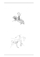
LQ-2070 Service Manual Adjustment 9. Insert a thin screwdriver into the drilled hole at the right edge of the rear CR guide shaft and adjust the platen gap by moving the screwdriver forward or backward until the gap is large enough for a 0.38 mm thickness gauge but too narrow for a 0.41 mm thickness gauge. 10. When the gap is correct at the 5th column, check the platen gap at the 80th, and then the 130th column positions. Figure 4-3 Platen Gap 11. If the platen gap is wider at the 5th column than the 130th column, adjust the parallelism for the rear CR guide shaft by moving the parallelism adjustment bushing backward. If the platen gap is more narrow for the 5th column than the 130th column, adjust the parallelism of the CR guide shaft by moving the parallelism adjustment bushing forward. Refer to the following figure. Figure 4-4 Adjusting the Parallelism of the CR Guide Shaft 12. Continue performing adjustment steps 8 to 11 until the platen gap is correct at all 3 positions. After completing the adjustment, remove the screwdriver from the rear CR guide shaft. 13. After inserting the ribbon mask in the ribbon mask holder and installing the printhead into CR assembly, tighten the 2 CBS screws (3 × 8,F/Zn) to attach the printhead. 14. Tighten the hexagon nut (standard, M4) securing the PG adjust lever. Rev. A 4-3
-
 1
1 -
2
-
3
-
4
-
5
-
6
-
7
-
8
-
9
-
10
-
11
-
12
-
13
-
14
-
15
-
16
-
17
-
18
-
19
-
20
-
21
-
22
-
23
-
24
-
25
-
26
-
27
-
28
-
29
-
30
-
31
-
32
-
33
-
34
-
35
-
36
-
37
-
38
-
39
-
40
-
41
-
42
-
43
-
44
-
45
-
46
-
47
-
48
-
49
-
50
-
51
-
52
-
53
-
54
-
55
-
56
-
57
-
58
-
59
-
60
-
61
-
62
-
63
-
64
-
65
-
66
-
67
-
68
-
69
-
70
-
71
-
72
-
73
-
74
-
75
-
76
-
77
-
78
-
79
-
80
-
81
-
82
-
83
-
84
-
85
-
86
-
87
-
88
-
89
-
90
-
91
-
92
-
93
-
94
-
95
-
96
-
97
-
98
-
99
-
100
-
101
-
102
-
103
-
104
-
105
-
106
-
107
-
108
-
109
-
110
-
 111
111 -
 112
112 -
 113
113 -
 114
114 -
 115
115 -
 116
116 -
 117
117 -
 118
118 -
 119
119 -
 120
120 -
 121
121 -
122
-
123
-
124
-
125
-
126
-
127
-
128
-
129
-
130
-
131
-
132
-
133
-
134
-
135
-
136
-
137
-
138
-
139
-
140
-
141
-
142
-
143
-
144
-
145
-
146
-
147
-
148
-
149
-
150
-
151
-
152
-
153
-
154
-
155
-
156
-
157
-
158
-
159
-
160
-
161
-
162
-
163
-
164
-
165
 |
 |
