Epson 2070 Service Manual - Page 84
Removing the Panel Board Assembly, Lock Cover for CN1 and the FFC
 |
UPC - 010343812277
View all Epson 2070 manuals
Add to My Manuals
Save this manual to your list of manuals |
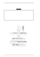
Page 84 highlights
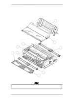
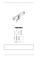
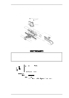
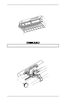
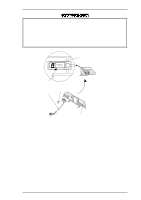
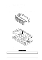
Disassembly and Assembly LQ-2070 Service Manual 3.2.2. Removing the Panel Board Assembly 1. Remove the printer cover and ribbon cartridge (see Section 3.2.1). 2. Release the left clips for the panel board assembly by pushing them from the cutout located on the inside front of the upper housing assembly. 3. Release the flexible flat cable (FFC) by pulling the lock cover for CN1, and then disconnect the FFC for CN1 from the C165 PNL board assembly. 4. Remove the panel board assembly from the upper housing assembly. CN1 Figure 3-4 Removing the Panel Board Assembly Assembly Notes Lock Cover for CN 1 CN 1 Slide CN 1 CN 1 FFC Exposed terminals face Figure 3-5 Lock Cover for CN1 and the FFC Before disconnecting the FFC from CN1, slide the lock cover for CN1 as shown in Figure 3-5, and release the FFC from CN1. After reconnecting the FFC for CN1, lock the lock cover . The FFC must be connected properly, as shown in Figure 3-5. Exposed terminals must be connected face upward against the C165 PNL board. 3-6 Rev.A
-
 1
1 -
2
-
3
-
4
-
5
-
6
-
7
-
8
-
9
-
10
-
11
-
12
-
13
-
14
-
15
-
16
-
17
-
18
-
19
-
20
-
21
-
22
-
23
-
24
-
25
-
26
-
27
-
28
-
29
-
30
-
31
-
32
-
33
-
34
-
35
-
36
-
37
-
38
-
39
-
40
-
41
-
42
-
43
-
44
-
45
-
46
-
47
-
48
-
49
-
50
-
51
-
52
-
53
-
54
-
55
-
56
-
57
-
58
-
59
-
60
-
61
-
62
-
63
-
64
-
65
-
66
-
67
-
68
-
69
-
70
-
71
-
72
-
73
-
74
-
75
-
76
-
77
-
78
-
 79
79 -
 80
80 -
 81
81 -
 82
82 -
 83
83 -
 84
84 -
 85
85 -
 86
86 -
 87
87 -
 88
88 -
 89
89 -
90
-
91
-
92
-
93
-
94
-
95
-
96
-
97
-
98
-
99
-
100
-
101
-
102
-
103
-
104
-
105
-
106
-
107
-
108
-
109
-
110
-
111
-
112
-
113
-
114
-
115
-
116
-
117
-
118
-
119
-
120
-
121
-
122
-
123
-
124
-
125
-
126
-
127
-
128
-
129
-
130
-
131
-
132
-
133
-
134
-
135
-
136
-
137
-
138
-
139
-
140
-
141
-
142
-
143
-
144
-
145
-
146
-
147
-
148
-
149
-
150
-
151
-
152
-
153
-
154
-
155
-
156
-
157
-
158
-
159
-
160
-
161
-
162
-
163
-
164
-
165
 |
 |
