Epson LX-80 User Manual - Page 142
side. To prevent noise, these cables should be shielded and con
 |
View all Epson LX-80 manuals
Add to My Manuals
Save this manual to your list of manuals |
Page 142 highlights
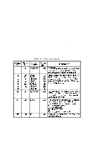
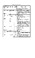
Table I-1, continued Notes: 1. The column heading "Direction" refers to the direction of signal flow as viewed from the printer. 2. "Return" denotes the twisted-pair return, to be connected at signal ground level. For the interface wiring, be sure to use a twisted-pair cable for each signal and to complete the connection on the return side. To prevent noise, these cables should be shielded and connected to the chassis of the host computer or the printer. 3. All interface conditions are based on TTL level. Both the rise and the fall times of each signal must be less than 0.2 microsecond. I-2
-
 1
1 -
2
-
3
-
4
-
5
-
6
-
7
-
8
-
9
-
10
-
11
-
12
-
13
-
14
-
15
-
16
-
17
-
18
-
19
-
20
-
21
-
22
-
23
-
24
-
25
-
26
-
27
-
28
-
29
-
30
-
31
-
32
-
33
-
34
-
35
-
36
-
37
-
38
-
39
-
40
-
41
-
42
-
43
-
44
-
45
-
46
-
47
-
48
-
49
-
50
-
51
-
52
-
53
-
54
-
55
-
56
-
57
-
58
-
59
-
60
-
61
-
62
-
63
-
64
-
65
-
66
-
67
-
68
-
69
-
70
-
71
-
72
-
73
-
74
-
75
-
76
-
77
-
78
-
79
-
80
-
81
-
82
-
83
-
84
-
85
-
86
-
87
-
88
-
89
-
90
-
91
-
92
-
93
-
94
-
95
-
96
-
97
-
98
-
99
-
100
-
101
-
102
-
103
-
104
-
105
-
106
-
107
-
108
-
109
-
110
-
111
-
112
-
113
-
114
-
115
-
116
-
117
-
118
-
119
-
120
-
121
-
122
-
123
-
124
-
125
-
126
-
127
-
128
-
129
-
130
-
131
-
132
-
133
-
134
-
135
-
136
-
 137
137 -
 138
138 -
 139
139 -
 140
140 -
 141
141 -
 142
142 -
 143
143 -
 144
144 -
 145
145 -
 146
146 -
 147
147 -
148
-
149
-
150
-
151
-
152
-
153
-
154
-
155
-
156
-
157
-
158
 |
 |
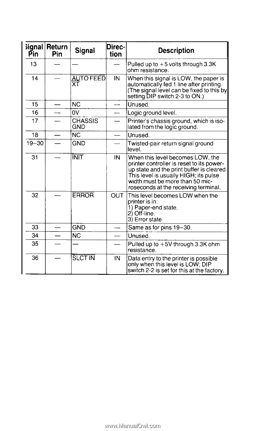
Table I-1, continued
Notes:
1.
The column heading “Direction” refers to the direction of signal
flow as viewed from the printer.
2. “Return” denotes the twisted-pair return, to be connected at signal
ground level. For the interface wiring, be sure to use a twisted-pair
cable for each signal and to complete the connection on the return
side. To prevent noise, these cables should be shielded and con-
nected to the chassis of the host computer or the printer.
3.
All interface conditions are based on TTL level. Both the rise and
the fall times of each signal must be less than 0.2 microsecond.
I-2