HP 3390 Service Manual - Page 120
ADF operation, ADF paper path and ADF sensors, Standby paper-loading mode
 |
View all HP 3390 manuals
Add to My Manuals
Save this manual to your list of manuals |
Page 120 highlights
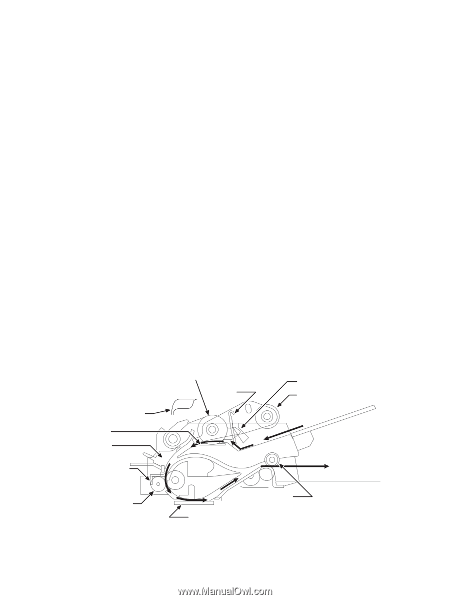
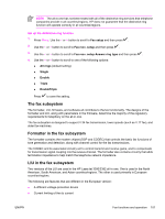
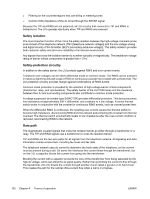
If the all-in-one detects a document in the ADF when a copy or scan is initiated (from the software or the control panel), the scan module moves to the left side of the scan tub and stops. The image is acquired as the paper is fed through the ADF past the scanner module. If no document is detected in the ADF, or if the model does not have an ADF, the scan module acquires the image from the flatbed glass while slowly moving within the scan tub. ADF operation Standby (paper-loading) mode: In standby mode, the pickup roller is up and the stack-stop is down, preventing the user from inserting the original document too far. When a document is inserted correctly, the paper-present sensor detects its presence. The standard operation of the ADF consists of the pick, feed, and lift steps. Pick: When it receives a copy or scan command, the ADF motor engages the gear train to lower the pickup-roller assembly and raise the stack-stop. The first roller, called the pre-pick roller, moves the top few sheets forward into the ADF. The next roller is the pickup roller. This roller contacts the ADF separation pad, which separates multiple pages into single sheets. Feed: The single sheet continues through the path. Along the way, the form sensor, which is a set distance from the ADF glass, detects the sheet. This alerts the scanner to start when the page reaches the glass. The scanner acquires the image, one raster line at a time, until it detects the end of the page. The page is then ejected. The pick and feed steps are repeated as long as paper is detected in the ADF input tray. Lift: When no more paper is detected in the ADF input tray and the form sensor detects the trailing edge of the last page, the last sheet is ejected and the motor turns in a sequence that lifts the pick roller assembly to standby (paper-loading) mode again. The ADF will not function when the ADF cover is open. The paper path is incomplete if the ADF cover is lifted from the glass. ADF paper path and ADF sensors The following diagram shows the ADF paper path. ADF door open flag Separation pad Cleanout Pick roller Stack stop Form sensor Paper present sensor Pre-pick roller Picks top sheet INPUT TRAY PAGE EJECTS FULLY OUTPUT AREA Prescan rollers Figure 4-15 ADF paper path ADF glass Postscan rollers 98 Chapter 4 Theory of operation ENWW
-
 1
1 -
2
-
3
-
4
-
5
-
6
-
7
-
8
-
9
-
10
-
11
-
12
-
13
-
14
-
15
-
16
-
17
-
18
-
19
-
20
-
21
-
22
-
23
-
24
-
25
-
26
-
27
-
28
-
29
-
30
-
31
-
32
-
33
-
34
-
35
-
36
-
37
-
38
-
39
-
40
-
41
-
42
-
43
-
44
-
45
-
46
-
47
-
48
-
49
-
50
-
51
-
52
-
53
-
54
-
55
-
56
-
57
-
58
-
59
-
60
-
61
-
62
-
63
-
64
-
65
-
66
-
67
-
68
-
69
-
70
-
71
-
72
-
73
-
74
-
75
-
76
-
77
-
78
-
79
-
80
-
81
-
82
-
83
-
84
-
85
-
86
-
87
-
88
-
89
-
90
-
91
-
92
-
93
-
94
-
95
-
96
-
97
-
98
-
99
-
100
-
101
-
102
-
103
-
104
-
105
-
106
-
107
-
108
-
109
-
110
-
111
-
112
-
113
-
114
-
 115
115 -
 116
116 -
 117
117 -
 118
118 -
 119
119 -
 120
120 -
 121
121 -
 122
122 -
 123
123 -
 124
124 -
 125
125 -
126
-
127
-
128
-
129
-
130
-
131
-
132
-
133
-
134
-
135
-
136
-
137
-
138
-
139
-
140
-
141
-
142
-
143
-
144
-
145
-
146
-
147
-
148
-
149
-
150
-
151
-
152
-
153
-
154
-
155
-
156
-
157
-
158
-
159
-
160
-
161
-
162
-
163
-
164
-
165
-
166
-
167
-
168
-
169
-
170
-
171
-
172
-
173
-
174
-
175
-
176
-
177
-
178
-
179
-
180
-
181
-
182
-
183
-
184
-
185
-
186
-
187
-
188
-
189
-
190
-
191
-
192
-
193
-
194
-
195
-
196
-
197
-
198
-
199
-
200
-
201
-
202
-
203
-
204
-
205
-
206
-
207
-
208
-
209
-
210
-
211
-
212
-
213
-
214
-
215
-
216
-
217
-
218
-
219
-
220
-
221
-
222
-
223
-
224
-
225
-
226
-
227
-
228
-
229
-
230
-
231
-
232
-
233
-
234
-
235
-
236
-
237
-
238
-
239
-
240
-
241
-
242
-
243
-
244
-
245
-
246
-
247
-
248
-
249
-
250
-
251
-
252
-
253
-
254
-
255
-
256
-
257
-
258
-
259
-
260
-
261
-
262
-
263
-
264
-
265
-
266
-
267
-
268
-
269
-
270
-
271
-
272
-
273
-
274
-
275
-
276
-
277
-
278
-
279
-
280
-
281
-
282
-
283
-
284
-
285
-
286
-
287
-
288
-
289
-
290
-
291
-
292
-
293
-
294
-
295
-
296
-
297
-
298
-
299
-
300
-
301
-
302
-
303
-
304
-
305
-
306
-
307
-
308
-
309
-
310
-
311
-
312
-
313
-
314
-
315
-
316
-
317
-
318
-
319
-
320
-
321
-
322
-
323
-
324
-
325
-
326
-
327
-
328
-
329
-
330
-
331
-
332
-
333
-
334
-
335
-
336
-
337
-
338
-
339
-
340
-
341
-
342
-
343
-
344
-
345
-
346
-
347
-
348
-
349
-
350
-
351
-
352
-
353
-
354
-
355
-
356
-
357
-
358
-
359
-
360
-
361
-
362
-
363
-
364
 |
 |