HP 3390 Service Manual - Page 21
Scanner and ADF,
 |
View all HP 3390 manuals
Add to My Manuals
Save this manual to your list of manuals |
Page 21 highlights
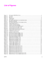
Figure 6-24 Figure 6-25 Figure 6-26 Figure 6-27 Figure 6-28 Figure 6-29 Figure 6-30 Figure 6-31 Figure 6-32 Figure 6-33 Figure 6-34 Figure 6-35 Figure 6-36 Figure 6-37 Figure 6-38 Figure 6-39 Figure 6-40 Figure 6-41 Figure 6-42 Figure 6-43 Figure 6-44 Figure 6-45 Figure 6-46 Figure 6-47 Figure 6-48 Figure 7-1 Figure 7-2 Figure 7-3 Figure 7-4 Figure 7-5 Figure 7-6 Figure 7-7 Figure 7-8 Figure 7-9 Figure 7-10 Figure 7-11 Figure 7-12 Figure 7-13 Figure 7-14 Figure 7-15 Figure 7-16 Figure 7-17 Figure 7-18 Figure 7-19 Figure 7-20 Figure 7-21 Figure 7-22 Figure 7-23 Figure 7-24 Figure 7-25 Jams in the duplex path (4 of 10 192 Jams in the duplex path (5 of 10 192 Jams in the duplex path (6 of 10 193 Jams in the duplex path (7 of 10 193 Jams in the duplex path (8 of 10 194 Jams in the duplex path (9 of 10 194 Jams in the duplex path (10 of 10 195 Jams in the ADF (1 of 10)...195 Jams in the ADF (2 of 10)...196 Jams in the ADF (3 of 10)...196 Jams in the ADF (4 of 10)...197 Jams in the ADF (5 of 10)...197 Jams in the ADF (6 of 10)...198 Jams in the ADF (7 of 10)...198 Jams in the ADF (8 of 10)...199 Jams in the ADF (9 of 10)...199 Jams in the ADF (10 of 10)...200 Jams in the convenience stapler (1 of 5 200 Jams in the convenience stapler (2 of 5 201 Jams in the convenience stapler (3 of 5 201 Jams in the convenience stapler (4 of 5 202 Jams in the convenience stapler (5 of 5 202 Engine test switch...239 Print-cartridge high-voltage connection points (right side 241 Print-cartridge high-voltage connection points (left side 241 Interface connectors...262 Formatter connectors...263 LIU connectors...264 Solenoids...264 Switches and sensors...265 Rollers and pads...266 PCAs (base unit)...267 Major components (base unit)...268 Scanner and ADF...269 Circuit diagram...270 Scanner and ADF assemblies...272 Scanner assemblies...274 ADF components...276 Convenience stapler components (HP LJ 3392 only 278 Formatter, LIU, HP jewel, and nameplate 280 External covers and panels...282 Internal components (1 of 4)...284 Internal components (2 of 4)...286 Internal components (3 of 4)...288 Internal components (4 of 4)...290 Engine-controller assembly...292 Main-drive assembly...294 Duplexing-drive assembly...296 Tray 2 cassette and tray 3 cassette/feeder 298 Duplexing assembly...300 ENWW xix
-
 1
1 -
2
-
3
-
4
-
5
-
6
-
7
-
8
-
9
-
10
-
11
-
12
-
13
-
14
-
15
-
 16
16 -
 17
17 -
 18
18 -
 19
19 -
 20
20 -
 21
21 -
 22
22 -
 23
23 -
 24
24 -
 25
25 -
 26
26 -
27
-
28
-
29
-
30
-
31
-
32
-
33
-
34
-
35
-
36
-
37
-
38
-
39
-
40
-
41
-
42
-
43
-
44
-
45
-
46
-
47
-
48
-
49
-
50
-
51
-
52
-
53
-
54
-
55
-
56
-
57
-
58
-
59
-
60
-
61
-
62
-
63
-
64
-
65
-
66
-
67
-
68
-
69
-
70
-
71
-
72
-
73
-
74
-
75
-
76
-
77
-
78
-
79
-
80
-
81
-
82
-
83
-
84
-
85
-
86
-
87
-
88
-
89
-
90
-
91
-
92
-
93
-
94
-
95
-
96
-
97
-
98
-
99
-
100
-
101
-
102
-
103
-
104
-
105
-
106
-
107
-
108
-
109
-
110
-
111
-
112
-
113
-
114
-
115
-
116
-
117
-
118
-
119
-
120
-
121
-
122
-
123
-
124
-
125
-
126
-
127
-
128
-
129
-
130
-
131
-
132
-
133
-
134
-
135
-
136
-
137
-
138
-
139
-
140
-
141
-
142
-
143
-
144
-
145
-
146
-
147
-
148
-
149
-
150
-
151
-
152
-
153
-
154
-
155
-
156
-
157
-
158
-
159
-
160
-
161
-
162
-
163
-
164
-
165
-
166
-
167
-
168
-
169
-
170
-
171
-
172
-
173
-
174
-
175
-
176
-
177
-
178
-
179
-
180
-
181
-
182
-
183
-
184
-
185
-
186
-
187
-
188
-
189
-
190
-
191
-
192
-
193
-
194
-
195
-
196
-
197
-
198
-
199
-
200
-
201
-
202
-
203
-
204
-
205
-
206
-
207
-
208
-
209
-
210
-
211
-
212
-
213
-
214
-
215
-
216
-
217
-
218
-
219
-
220
-
221
-
222
-
223
-
224
-
225
-
226
-
227
-
228
-
229
-
230
-
231
-
232
-
233
-
234
-
235
-
236
-
237
-
238
-
239
-
240
-
241
-
242
-
243
-
244
-
245
-
246
-
247
-
248
-
249
-
250
-
251
-
252
-
253
-
254
-
255
-
256
-
257
-
258
-
259
-
260
-
261
-
262
-
263
-
264
-
265
-
266
-
267
-
268
-
269
-
270
-
271
-
272
-
273
-
274
-
275
-
276
-
277
-
278
-
279
-
280
-
281
-
282
-
283
-
284
-
285
-
286
-
287
-
288
-
289
-
290
-
291
-
292
-
293
-
294
-
295
-
296
-
297
-
298
-
299
-
300
-
301
-
302
-
303
-
304
-
305
-
306
-
307
-
308
-
309
-
310
-
311
-
312
-
313
-
314
-
315
-
316
-
317
-
318
-
319
-
320
-
321
-
322
-
323
-
324
-
325
-
326
-
327
-
328
-
329
-
330
-
331
-
332
-
333
-
334
-
335
-
336
-
337
-
338
-
339
-
340
-
341
-
342
-
343
-
344
-
345
-
346
-
347
-
348
-
349
-
350
-
351
-
352
-
353
-
354
-
355
-
356
-
357
-
358
-
359
-
360
-
361
-
362
-
363
-
364
 |
 |
