HP Integrity Superdome SX1000 User Guide, Sixth Edition - HP Integrity Superdo - Page 161
Table 5-3, Floor-Loading Terms, Average Floor Loading, Typical Raised-Floor Site, Definition
 |
View all HP Integrity Superdome SX1000 manuals
Add to My Manuals
Save this manual to your list of manuals |
Page 161 highlights
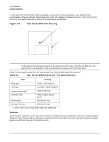
Site Preparation Facility Guidelines Floor-Loading Terms Table 5-3 defines floor-loading terms. Table 5-3 Floor-Loading Terms Term Dead load Live load Concentrated load Ultimate load Rolling load Average floor load Definition Weight of the raised-panel floor system, including the understructure. Expressed in lb/ft2 (kg/m2). Load the floor system can safely support. Expressed in lb/ft2 (kg/m2). Load a floor panel can support on a 1-in2 (6.45 cm2) area at the panel's weakest point (typically the center of the panel), without the surface of the panel deflecting more than a predetermined amount. Maximum load (per floor panel) the floor system can support without failure. Failure expressed by floor panel(s) breaking or bending. Ultimate load is usually stated as load per floor panel. Load a floor panel can support (without failure) when a wheel of specified diameter and width is rolled across the panel. Computed by dividing total equipment weight by the area of its footprint. This value is expressed in lb/ft2 (kg/m2). Average Floor Loading The average floor load value, defined in Table 5-4, is not appropriate for addressing raised-floor ratings at the floor grid spacing level. However, it is useful for determining floor-loading at the building level, such as the area of solid floor or span of raised-floor tiles covered by the Superdome server footprint. Typical Raised-Floor Site This section contains an example of a computer room raised-floor system that is satisfactory for the installation of a Superdome server. Based on specific information provided by Hewlett-Packard, Tate Access Floors has approved its Series 800 all-steel access floor with bolt-together stringers and 24 in. (61.0 cm) by 24 in. (61.0 cm) floor panels. Due to the large amount of floor panel material that must be removed for the purpose of routing cables, this particular floor must be braced as shown in Figure 5-6. Chapter 5 149
-
 1
1 -
2
-
3
-
4
-
5
-
6
-
7
-
8
-
9
-
10
-
11
-
12
-
13
-
14
-
15
-
16
-
17
-
18
-
19
-
20
-
21
-
22
-
23
-
24
-
25
-
26
-
27
-
28
-
29
-
30
-
31
-
32
-
33
-
34
-
35
-
36
-
37
-
38
-
39
-
40
-
41
-
42
-
43
-
44
-
45
-
46
-
47
-
48
-
49
-
50
-
51
-
52
-
53
-
54
-
55
-
56
-
57
-
58
-
59
-
60
-
61
-
62
-
63
-
64
-
65
-
66
-
67
-
68
-
69
-
70
-
71
-
72
-
73
-
74
-
75
-
76
-
77
-
78
-
79
-
80
-
81
-
82
-
83
-
84
-
85
-
86
-
87
-
88
-
89
-
90
-
91
-
92
-
93
-
94
-
95
-
96
-
97
-
98
-
99
-
100
-
101
-
102
-
103
-
104
-
105
-
106
-
107
-
108
-
109
-
110
-
111
-
112
-
113
-
114
-
115
-
116
-
117
-
118
-
119
-
120
-
121
-
122
-
123
-
124
-
125
-
126
-
127
-
128
-
129
-
130
-
131
-
132
-
133
-
134
-
135
-
136
-
137
-
138
-
139
-
140
-
141
-
142
-
143
-
144
-
145
-
146
-
147
-
148
-
149
-
150
-
151
-
152
-
153
-
154
-
155
-
 156
156 -
 157
157 -
 158
158 -
 159
159 -
 160
160 -
 161
161 -
 162
162 -
 163
163 -
 164
164 -
 165
165 -
 166
166 -
167
-
168
-
169
-
170
-
171
-
172
-
173
-
174
-
175
-
176
-
177
-
178
-
179
-
180
-
181
-
182
-
183
-
184
-
185
-
186
-
187
-
188
-
189
-
190
-
191
-
192
-
193
-
194
-
195
-
196
-
197
-
198
-
199
-
200
-
201
-
202
-
203
-
204
-
205
-
206
-
207
-
208
-
209
-
210
-
211
-
212
-
213
-
214
-
215
-
216
-
217
-
218
-
219
-
220
-
221
-
222
-
223
-
224
-
225
-
226
-
227
-
228
-
229
-
230
-
231
-
232
-
233
-
234
-
235
-
236
-
237
-
238
-
239
-
240
-
241
-
242
-
243
-
244
-
245
-
246
-
247
-
248
-
249
-
250
-
251
-
252
-
253
-
254
-
255
-
256
-
257
-
258
-
259
-
260
-
261
-
262
-
263
-
264
-
265
-
266
-
267
-
268
-
269
-
270
-
271
-
272
-
273
-
274
-
275
-
276
-
277
-
278
-
279
-
280
-
281
-
282
-
283
-
284
-
285
-
286
-
287
-
288
-
289
-
290
-
291
-
292
-
293
-
294
-
295
-
296
-
297
-
298
-
299
-
300
-
301
-
302
-
303
-
304
-
305
-
306
-
307
-
308
-
309
-
310
-
311
-
312
-
313
-
314
-
315
-
316
-
317
-
318
-
319
-
320
-
321
-
322
-
323
-
324
-
325
-
326
-
327
-
328
-
329
-
330
-
331
-
332
 |
 |
