HP OmniBook 500 HP OmniBook 500 (FA) - Corporate Evaluator's Guide Edition 4 - Page 105
panel slightly to the right and lift it out.
 |
View all HP OmniBook 500 manuals
Add to My Manuals
Save this manual to your list of manuals |
Page 105 highlights
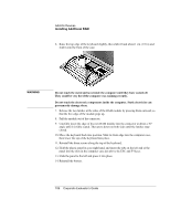
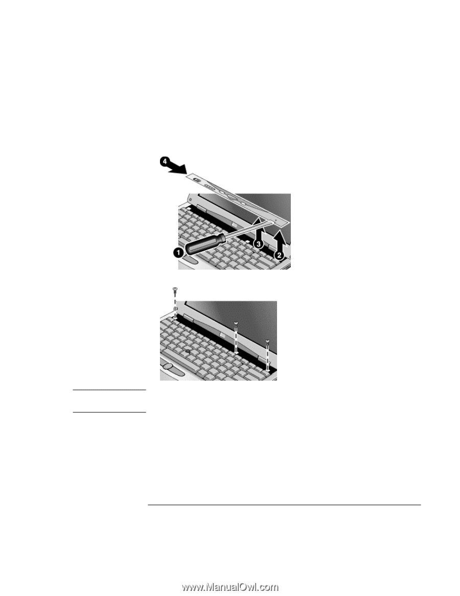
Add-On Devices Installing Additional RAM 4. Remove the plastic panel above the keyboard (containing the power button and keyboard status lights). Pry the right end of the panel up with a small, flat-blade screwdriver, then lift the end until the panel unsnaps above the F12 key. Slide the panel slightly to the right and lift it out. 5. Remove the three screws holding the top of the keyboard. CAUTION When opening the keyboard, be careful not to pull on the cables connecting the keyboard to the computer. Corporate Evaluator's Guide 105
-
 1
1 -
2
-
3
-
4
-
5
-
6
-
7
-
8
-
9
-
10
-
11
-
12
-
13
-
14
-
15
-
16
-
17
-
18
-
19
-
20
-
21
-
22
-
23
-
24
-
25
-
26
-
27
-
28
-
29
-
30
-
31
-
32
-
33
-
34
-
35
-
36
-
37
-
38
-
39
-
40
-
41
-
42
-
43
-
44
-
45
-
46
-
47
-
48
-
49
-
50
-
51
-
52
-
53
-
54
-
55
-
56
-
57
-
58
-
59
-
60
-
61
-
62
-
63
-
64
-
65
-
66
-
67
-
68
-
69
-
70
-
71
-
72
-
73
-
74
-
75
-
76
-
77
-
78
-
79
-
80
-
81
-
82
-
83
-
84
-
85
-
86
-
87
-
88
-
89
-
90
-
91
-
92
-
93
-
94
-
95
-
96
-
97
-
98
-
99
-
 100
100 -
 101
101 -
 102
102 -
 103
103 -
 104
104 -
 105
105 -
 106
106 -
 107
107 -
 108
108 -
 109
109 -
 110
110 -
111
-
112
-
113
-
114
-
115
-
116
-
117
-
118
-
119
-
120
-
121
-
122
-
123
-
124
-
125
-
126
-
127
-
128
-
129
-
130
-
131
-
132
-
133
-
134
-
135
-
136
-
137
-
138
-
139
-
140
-
141
-
142
-
143
-
144
-
145
-
146
-
147
-
148
-
149
-
150
-
151
-
152
-
153
-
154
-
155
-
156
-
157
-
158
-
159
-
160
-
161
-
162
-
163
-
164
-
165
-
166
-
167
-
168
-
169
-
170
-
171
-
172
-
173
-
174
-
175
-
176
-
177
-
178
-
179
-
180
-
181
-
182
-
183
-
184
-
185
-
186
-
187
-
188
-
189
-
190
-
191
-
192
-
193
-
194
-
195
-
196
-
197
-
198
-
199
-
200
-
201
-
202
-
203
-
204
-
205
-
206
-
207
-
208
-
209
-
210
-
211
-
212
-
213
-
214
-
215
-
216
-
217
-
218
-
219
-
220
-
221
-
222
-
223
-
224
-
225
-
226
-
227
-
228
-
229
-
230
-
231
-
232
-
233
-
234
-
235
 |
 |
Add-On Devices
Installing Additional RAM
Corporate Evaluator’s Guide
105
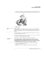
4.
Remove the plastic panel above the keyboard (containing the power button and
keyboard status lights). Pry the right end of the panel up with a small, flat-blade
screwdriver, then lift the end until the panel unsnaps above the F12 key. Slide the
panel slightly to the right and lift it out.
5.
Remove the three screws holding the top of the keyboard.
CAUTION
When opening the keyboard, be careful not to pull on the cables connecting the
keyboard to the computer.