HP Scitex LX600 HP Designjet L65500 Printer and HP Scitex LX Printer Family - - Page 35
Check resistances, Check connections
 |
View all HP Scitex LX600 manuals
Add to My Manuals
Save this manual to your list of manuals |
Page 35 highlights
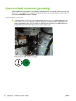
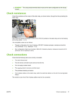
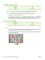
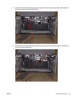
WARNING! The curing module terminal block must use the same configuration as the drying module. Check resistances Check the resistance at the output of the static relay, as shown below, through the hole protecting the static relay. Also check the resistance between A2-B2, A2-C2, B2-C2 (marked on the static relay and on the heating and curing cables: 1, 2, 3). The acceptable values are as follows. ● Triangle configuration (low input tri-phase, 200-220 V between phases): resistance should be 16 Ω (minimum: 15 Ω , maximum: 17 Ω). ● Star configuration (high input tri-phase, 380-415 V between phases): resistance should be 32 Ω (minimum: 30 Ω, maximum: 34 Ω). Check connections Check that the following items are correctly connected. ● The main interconnect ● The left remote controller board (remove the left trim) ● The ink supply module board ● The capping station's remote controller board ● The printhead cleaning roll station ● The tri-phase cables on the static relay: within the electrical cabinet, on the left, the two big black relays) The neutral or zero line of the tri-phase cables must not be connected. ENWW Check resistances 31
-
 1
1 -
2
-
3
-
4
-
5
-
6
-
7
-
8
-
9
-
10
-
11
-
12
-
13
-
14
-
15
-
16
-
17
-
18
-
19
-
20
-
21
-
22
-
23
-
24
-
25
-
26
-
27
-
28
-
29
-
 30
30 -
 31
31 -
 32
32 -
 33
33 -
 34
34 -
 35
35 -
 36
36 -
 37
37 -
 38
38 -
 39
39 -
 40
40 -
41
-
42
-
43
-
44
-
45
-
46
-
47
-
48
-
49
-
50
-
51
-
52
-
53
-
54
-
55
-
56
-
57
-
58
-
59
-
60
-
61
-
62
-
63
-
64
-
65
-
66
-
67
-
68
-
69
-
70
-
71
-
72
-
73
-
74
-
75
-
76
-
77
-
78
-
79
-
80
-
81
-
82
-
83
-
84
-
85
-
86
 |
 |