JVC GY-DV300U 108 pg. instruction manual on the GY-DV300U Pro-DV Camcorder (PD
JVC GY-DV300U - 1/3" 3-ccd Dv Camcorder Manual
 |
View all JVC GY-DV300U manuals
Add to My Manuals
Save this manual to your list of manuals |
JVC GY-DV300U manual content summary:
- JVC GY-DV300U | 108 pg. instruction manual on the GY-DV300U Pro-DV Camcorder (PD - Page 1
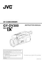
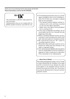
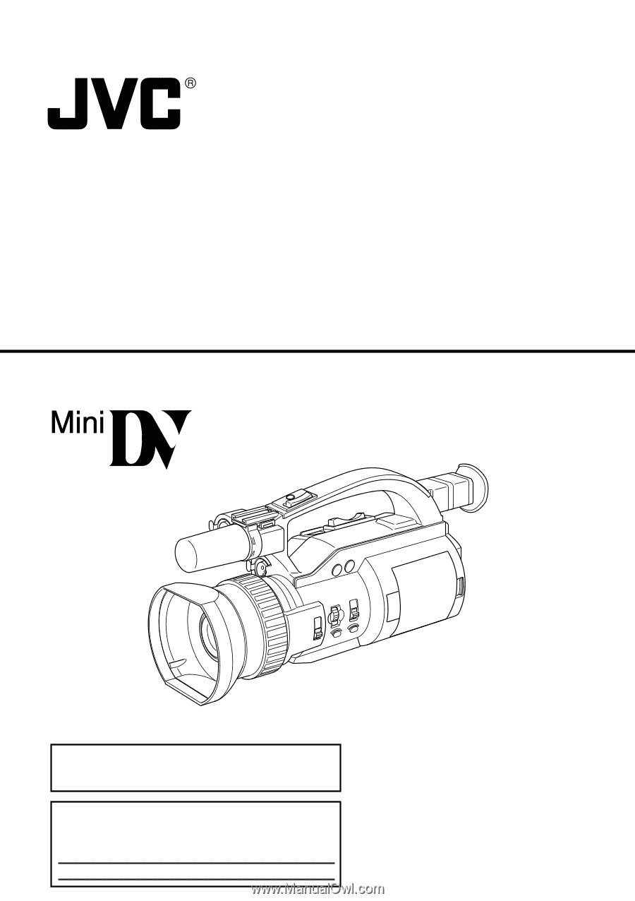
DV CAMCORDER GY-DV300 INSTRUCTION MANUAL Thank you for purchasing this JVC product. Before operating this unit, please read the instructions carefully to ensure the best possible performance. For Customer Use : Enter below the Serial No. which is located on the body. Retain this information for - JVC GY-DV300U | 108 pg. instruction manual on the GY-DV300U Pro-DV Camcorder (PD - Page 2
follow the manufacturer's instructions, and should use a mounting kit approved by the appliance designed to operate from battery power, refer to the operating instructions. 10. This appliance service. 18. When replacement parts are required, be sure the service technician has used replacement parts - JVC GY-DV300U | 108 pg. instruction manual on the GY-DV300U Pro-DV Camcorder (PD - Page 3
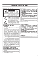
presence of important operating and maintenance (servicing) instructions in the literature accompanying the appliance. INFORMATION FOR USA INFORMATION This equipment has been tested and found to comply with the limits for a Class B digital device, pursuant to Part 15 of the FCC Rules. These limits - JVC GY-DV300U | 108 pg. instruction manual on the GY-DV300U Pro-DV Camcorder (PD - Page 4
Thank you for purchasing the DV Camcorder GY-DV300. These instructions are for the GY-DV300U. This camcorder is a MiniDV video system format camcorder. Videocassettes that are not marked with the MiniDV symbol cannot be used with this unit. ● The following phenomena may occur when tapes recorded - JVC GY-DV300U | 108 pg. instruction manual on the GY-DV300U Pro-DV Camcorder (PD - Page 5
time code possible. ● Edit search function for convenient recording review ● Variable scan shutter Eliminates flicker when shooting other screen DV (i. LINK) connector DV connector (4-pin) provided. Enables transfer of digital data to other equipment provided with DV connector. ● Built-in camera- - JVC GY-DV300U | 108 pg. instruction manual on the GY-DV300U Pro-DV Camcorder (PD - Page 6
Screen 90 SYSTEM Menu Screen 91 DISPLAY Menu Screen 94 CAMERA Menu Screen 96 OPERATION Menu Screen 98 CLOCK/TC Menu Screen 99 VTR Menu Screen 99 TROUBLESHOOTING Alarm Indications and Actions 100 In case of Difficulty 102 OTHERS Displaying the Hour Meter Display 104 Specifications 105 6 - JVC GY-DV300U | 108 pg. instruction manual on the GY-DV300U Pro-DV Camcorder (PD - Page 7
, etc., or near devices emitting radio waves, such as transceivers or cellular phones. ● If a transceiver or cellular telephone is used closed to the GY-DV300 while the camera-shake compensation function is in use, the camera image may flicker due to the influence of emitted electromagnetic waves - JVC GY-DV300U | 108 pg. instruction manual on the GY-DV300U Pro-DV Camcorder (PD - Page 8
the unit is not in use, be sure to set the POWER switch to OFF in order to reduce power consumption. ● Cleaning the camera body: Wipe the body with and do not wipe it with a cloth soaked in such a liquid. ● The camera may be unstable for a few seconds immediately after the power is turned on, but - JVC GY-DV300U | 108 pg. instruction manual on the GY-DV300U Pro-DV Camcorder (PD - Page 9
(inspection) to prevent troubles that may be caused by the sudden occurrence of failure. As the replacement, adjustment and servicing of parts require advanced skill and equipment, please consult the person in charge of professional video equipment at your nearest JVC-authorized service agent. Head - JVC GY-DV300U | 108 pg. instruction manual on the GY-DV300U Pro-DV Camcorder (PD - Page 10
instructions of this document. Note 5) Perform head cleaning before using the GY-DV300 in the LP mode. Videocassette to be Used ● Use JVC videocassette tapes marked with MiniDV for this unit. Please use on digital video units that do not support the LP mode. ● Videocassettes cannot be used upside - JVC GY-DV300U | 108 pg. instruction manual on the GY-DV300U Pro-DV Camcorder (PD - Page 11
drum and tape guides are covered with camera under conditions where the temperature environment changes. After moving the unit, do not use until the internal parts GY-DV300 in a plastic bag and seal it before transporting the camera. Leave the GY-DV300 in the sealed plastic bag until the camera - JVC GY-DV300U | 108 pg. instruction manual on the GY-DV300U Pro-DV Camcorder (PD - Page 12
ND FILTER ON OFF IRIS FOCUS AUTO MANU PUSH AUTO q wer yt PROFESSINAL OPEN DV CAMCORDER GY-DV300 !1 i o 1 FOCUS ring Manual focus ring. Set the FOCUS switch 5 to "MANUAL" before turning this ring to adjust the focus manually. If the FOCUS switch is set to "AUTO", this ring will not work - JVC GY-DV300U | 108 pg. instruction manual on the GY-DV300U Pro-DV Camcorder (PD - Page 13
When the button is released, the manual mode is restored. When the [ GY-DV300 is in the recording mode. It blinks slowly when the battery pack is exhausted and when there is about 3 minutes or less tape remaining. When the tape has run out, or the VTR enters the warning mode, it blinks quickly. Use - JVC GY-DV300U | 108 pg. instruction manual on the GY-DV300U Pro-DV Camcorder (PD - Page 14
with the operating mode of the GY-DV300. When used in the shooting mode, the switch is set to "CAM-A" or "CAM-B". When used in the VTR playback mode, it the video signal input from the DV connector. I [GAIN] Sensitivity selector button This button is for manual adjustment of sensitivity. It works - JVC GY-DV300U | 108 pg. instruction manual on the GY-DV300U Pro-DV Camcorder (PD - Page 15
MANUAL mode, the current shutter speed setting is shown on the LCD screen or the viewfinder screen for about 3 seconds. In this condition, it possible to set the shutter speed of the GY-DV300 CH-1/CH-2 AUDIO] CH-1/CH-2 audio input selector switch Used to select the audio source input to the CH1/CH-2 - JVC GY-DV300U | 108 pg. instruction manual on the GY-DV300U Pro-DV Camcorder (PD - Page 16
switches the setting between color bar output and camera image output. ● Pressing this button in button ● Used when white balance adjustment is performed in the shooting mode. To use this button for after which white balance adjustment of the GY-DV300 becomes possible. The white balance adjustment - JVC GY-DV300U | 108 pg. instruction manual on the GY-DV300U Pro-DV Camcorder (PD - Page 17
during playback, still picture playback, or forward search initiates reverse search. S LCD monitor screen ● Shows a color camera image or the VTR playback picture. It is also used for displaying the following: • Menu setting screens • Characters showing the whether the GYDV300 is set to shooting - JVC GY-DV300U | 108 pg. instruction manual on the GY-DV300U Pro-DV Camcorder (PD - Page 18
CONTROLS, INDICATORS AND CONNECTORS Left Side Section #7 MIC 1 IN MIC 2 IN EARPHONE DV Y/C OUT LINE CH-2 OUT CH-1 VIDEO OUT #6 #2#5#4 #3 #1 U [VIDEO OUT] Video output connector (RCA) Output connector for composite video signal. Outputs the input video signal and - JVC GY-DV300U | 108 pg. instruction manual on the GY-DV300U Pro-DV Camcorder (PD - Page 19
[DV] DV connector Using a DV cable (optional), a digital video component with DV connector can be connected here. To record DV GY-DV300, never leave the unit with this cover left open. • The GY-DV300 does not function if the cassette cover is not closed. [ Microphone holder attachment base Use - JVC GY-DV300U | 108 pg. instruction manual on the GY-DV300U Pro-DV Camcorder (PD - Page 20
supply (phantom microphone), set the +48V MIC2 item on the SYSTEM [1/2] menu screen to ON. This connector will then supply +48 V DC current. When using a microphone other than a phantom microphone, set the +48V MIC2 item to OFF. Memo: • The audio input channel is selected with the CH-1/CH-2 audio - JVC GY-DV300U | 108 pg. instruction manual on the GY-DV300U Pro-DV Camcorder (PD - Page 21
quicker the zoom action. ● In the VTR playback mode, this lever is used for adjusting the playback sound level. Pressing the lever in the + direction start and stop of recording from the handle top section. When the GY-DV300 is in the shooting mode, pressing this button starts the recording. Pressing - JVC GY-DV300U | 108 pg. instruction manual on the GY-DV300U Pro-DV Camcorder (PD - Page 22
the viewfinder screen. Status screens (screens for use in checking the current camera settings) Event indications Alarm indications Menu setting the shooting mode Vertically inverted display in the shooting mode Battery symbol For a part of the status indicators it is possible to select whether or - JVC GY-DV300U | 108 pg. instruction manual on the GY-DV300U Pro-DV Camcorder (PD - Page 23
indication appears. 5 Remaining battery power indication The remaining battery power is indicated by four different indicators. 6 Camera-shake compensation on indication Fully charged battery Blinking indicator (no remaining battery power) Displayed when the camera-shake compensation function - JVC GY-DV300U | 108 pg. instruction manual on the GY-DV300U Pro-DV Camcorder (PD - Page 24
setting is 0 dB or ALC. It is not shown when the shooting mode is AUTO, or the AE item is set to ON. 0 Manual white balance Displayed when manual white balance adjustment is enabled (when mode indication the WHITE BALANCE item is set to PUSH AUTO on the OPERATION menu screen). Indicates - JVC GY-DV300U | 108 pg. instruction manual on the GY-DV300U Pro-DV Camcorder (PD - Page 25
mode is AUTO (when the MODE item is set to AUTO on the TOP MENU screen). ˜: Displayed when the shooting mode is MANUAL (when the MODE item is set to MANUAL on the TOP MENU screen). B Filter indication ND: Displayed when the ND filter switch is set to ON. C Iris F-value indication - JVC GY-DV300U | 108 pg. instruction manual on the GY-DV300U Pro-DV Camcorder (PD - Page 26
inverted display indications in the shooting mode Remaining battery power indication The remaining battery power is indicated by four different indicators. : Fully charged battery : Remaining battery power is low : No remaining battery power (blinking) VTR operation mode indication ● symbol - JVC GY-DV300U | 108 pg. instruction manual on the GY-DV300U Pro-DV Camcorder (PD - Page 27
mode status indications q w VOL. e r t P L AY DV No. Item Contents 1 Audio playback volume Displayed in the VTR mode. , after the tape runs, the indication appears. 5 Remaining battery power indication The remaining battery power is indicated by four different indicators. Fully charged - JVC GY-DV300U | 108 pg. instruction manual on the GY-DV300U Pro-DV Camcorder (PD - Page 28
set to OFF on the DISPLAY [2/2] menu screen. Recorded data is show during playback, fast forward and rewind operations. During recording, the data from the DV connector is shown. The current data is shown in the stop mode. The indication is enabled/disabled by selecting the TIME/DATE item on the - JVC GY-DV300U | 108 pg. instruction manual on the GY-DV300U Pro-DV Camcorder (PD - Page 29
Event Indications When the gain and shutter speed are changed manually, the set condition is displayed for about 3 seconds at the time the change is made. Event display area Event display area Set Condition Contents of - JVC GY-DV300U | 108 pg. instruction manual on the GY-DV300U Pro-DV Camcorder (PD - Page 30
When remaining battery power or remaining tape is low. • Improper operation attempted. • Abnormality generated in the GY-DV300. Warning to "SAVE") is loaded. Displayed if an attempt to record is made when no DV signal is input. Displayed when attempt to record a copy-guard protected signal is made - JVC GY-DV300U | 108 pg. instruction manual on the GY-DV300U Pro-DV Camcorder (PD - Page 31
LEV EL 1 0 S YS T EM S E T . . D I S PLAY SE T . . CAME RA S E T [ C AM - A ] . . OPER AT I ON [ CAM- A ] . . C LOC K / TC . . MENU A L L R ESE T CANCE L EX I T Used for making a variety of settings. See "MENU Setting Screen" on page 86. Auto White Balance Indication AUTO WH I TE OPERATION - JVC GY-DV300U | 108 pg. instruction manual on the GY-DV300U Pro-DV Camcorder (PD - Page 32
TELE CONVERSION LENS WIDE CONVERSION LENS DV CAMCORDER CH-1 CH-2 AUDIO LEVEL ND FILTER ON OFF IRIS FOCUS AUTO MANU PUSH AUTO PROFESSINAL DV CAMCORDER GY-DV300 OPEN NETWORK PACK PC KA-DV300 AC AC ADAPTER/BATTERY CHARGER AA-P30 RECHARGEABLE BATTERY PACK BN-V428 ACCESSORY KIT TRIPOD 32 - JVC GY-DV300U | 108 pg. instruction manual on the GY-DV300U Pro-DV Camcorder (PD - Page 33
, see the instruction manual for the AA-P30. CAUTION: ● Do not disconnect or connect the DC cable or AC cord while recording is taking place. ● Remaining battery power indication when the AC adapter is used When the optional Network Pack KA-DV300 is connected, the remaining battery power indication - JVC GY-DV300U | 108 pg. instruction manual on the GY-DV300U Pro-DV Camcorder (PD - Page 34
For details, see the instruction manual for the AAP30. Attaching the Battery Pack on the GY-DV300 If the DC cable is connected to the GY-DC300, unplug the cable. 1. Hold the battery pack with the connector side facing the GY-DC300. 2. While pressing the battery pack against the GY- DC300, slide it - JVC GY-DV300U | 108 pg. instruction manual on the GY-DV300U Pro-DV Camcorder (PD - Page 35
replace with a fully charged battery pack. After the no remaining battery power warning appears, the GY-DV300 automatically stops operation if the battery power operation is continued. Battery Pack Continuous Operating Time (25°C) GY-DV300 only When KA-DV300 in use BN-V428 Approx. 120 min - JVC GY-DV300U | 108 pg. instruction manual on the GY-DV300U Pro-DV Camcorder (PD - Page 36
PREPARATIONS Attaching the Microphone (optional) Using the optional KA-A33 microphone holder allows the optional microphone attachment screw on the MIC 2 IN microphone holder to secure the holder to the GY-DV300. EARPHONE DV Y/C OUT LINE CH-2 OUT CH-1 VIDEO OUT 2. Turn the knob on the microphone - JVC GY-DV300U | 108 pg. instruction manual on the GY-DV300U Pro-DV Camcorder (PD - Page 37
REC START/STOP button to start recording. The GY-DV300 starts up in the VTR playback mode. The camera image does not appear in the viewfinder or to "OFF". 3. Remove the battery pack or the power supply to the DC INPUT connector. (When the GY-DV300 is not going to be used for at long time.) CAUTION: - JVC GY-DV300U | 108 pg. instruction manual on the GY-DV300U Pro-DV Camcorder (PD - Page 38
videocassette tape marked MiniDV. ● To record, slide the switch on the back for use in preventing accidental erasure to the "REC" side. ● Remove any the tape slack before loading. 1. Slide the EJECT switch on the top section of the GY-DV300 and then open the cassette cover. 2. Insert a videocassette - JVC GY-DV300U | 108 pg. instruction manual on the GY-DV300U Pro-DV Camcorder (PD - Page 39
of the LCD screen. Closing the LCD Screen Return the direction of the LCD screen to the normal position, and then close it into the camera body. 39 - JVC GY-DV300U | 108 pg. instruction manual on the GY-DV300U Pro-DV Camcorder (PD - Page 40
PREPARATIONS FOR OPERATION Adjusting the Viewfinder Adjusting the Position of the Viewfinder To facilitate low-angle shooting, the viewfinder can be turned approximately 75° upward. Underside Diopter adjustment knob Diopter Adjustment Move the diopter adjustment knob on the underside of the - JVC GY-DV300U | 108 pg. instruction manual on the GY-DV300U Pro-DV Camcorder (PD - Page 41
-in clock should be set. Powered by the built-in rechargeable backup battery, the set date and time data are retained and continue to count the CLOCK/ TC item, and then press the SELECT dial in the direction of the camera body. ● The CLOCK/TC menu screen appears. 4. Make settings on the CLOCK/TC - JVC GY-DV300U | 108 pg. instruction manual on the GY-DV300U Pro-DV Camcorder (PD - Page 42
in 1 and 2 above to set the month, day, year, hours, minutes. The digits indicating seconds cannot be set. 4 Press the SELECT dial in sync with a time The CLOCK/TC menu screen returns. 8. To return to the normal screen, use either of the following methods. Press the MENU button or Return to the TOP - JVC GY-DV300U | 108 pg. instruction manual on the GY-DV300U Pro-DV Camcorder (PD - Page 43
displayed. During DV signal input: The date and time from the DV connector are displayed 4:3 N E T R E MOTE ON SET UP OFF PAGE BACK 2. Use the DATE REC item on the SYSTEM [2/2] menu screen to select the mode in data are recorded when color bars and camera image are output. ● BARS: Date and - JVC GY-DV300U | 108 pg. instruction manual on the GY-DV300U Pro-DV Camcorder (PD - Page 44
then set the date and time and time code data again. However, it is possible to use the GY-DV300 even if the built-in battery is discharged but the date and time and time code data cannot be recorded. How to charge AC outlet DC IN AC adapter AA-P30 1. - JVC GY-DV300U | 108 pg. instruction manual on the GY-DV300U Pro-DV Camcorder (PD - Page 45
the procedure described in 1 and 2 above to set the desired value for all digits. 4 The setting values are confirmed and entered when the frame digit blinks and the SELECT dial is pressed. 4. When setting of all the digits is completed, rotate the SELECT dial to align the cursor with the PAGE BACK - JVC GY-DV300U | 108 pg. instruction manual on the GY-DV300U Pro-DV Camcorder (PD - Page 46
and then press the SELECT dial. 5. To return to the normal screen, use either of the following methods. Press the MENU button or Return to the TOP playback mode : The time code recorded on the tape is displayed. During DV signal recording: The current value of the built-in time code generator is - JVC GY-DV300U | 108 pg. instruction manual on the GY-DV300U Pro-DV Camcorder (PD - Page 47
, shutter speed, gain, white balance, audio recording level, and camerashake compensation. AUTO shooting The GY-DV300 is adjusted automatically. MANUAL shooting Make settings as desired on the OPERATION menu screen. Adjustments can be made using the GY-DV300's operation buttons and dial, etc. 47 - JVC GY-DV300U | 108 pg. instruction manual on the GY-DV300U Pro-DV Camcorder (PD - Page 48
item setting area is seen blinking, and settings can now be changed. 4. Rotate the SELECT dial to set to AUTO or MANUAL. AUTO : Auto shooting mode MANUAL : Manual shooting mode 5. Press the SELECT dial. ● The setting area stops blinking and the setting is confirmed and entered. 6. Rotate the SELECT - JVC GY-DV300U | 108 pg. instruction manual on the GY-DV300U Pro-DV Camcorder (PD - Page 49
microphone and a microphone connected to the MIC 1 input connector cannot be used at the same time. When using the GY-DV300 with the built-in microphone or a microphone connected to the MIC 1 input connector, select which one to use by setting the MIC1 INPUT SEL item on the SYSTEM [1/2] menu screen - JVC GY-DV300U | 108 pg. instruction manual on the GY-DV300U Pro-DV Camcorder (PD - Page 50
: Setting for the microphone connected to the MIC 2 input connector. ● Set to ON when a phantom microphone is used. ● Set to OFF when other microphone type than phantom microphone is used. CAUTION: ● Confirm that the +48V MIC1 or +48V MIC2 items are set to OFF before connecting another microphone - JVC GY-DV300U | 108 pg. instruction manual on the GY-DV300U Pro-DV Camcorder (PD - Page 51
monitor output signal is monaural. * In the shooting mode, sound is not output from the built-in speaker. Select the audio channel to be monitored using the MONITOR switch. "CH-1" : The signal input to the CH-1 channel is output. "MIX" : The sound input to the CH1 and CH2 channels is output - JVC GY-DV300U | 108 pg. instruction manual on the GY-DV300U Pro-DV Camcorder (PD - Page 52
ON OFF IRIS FOCUS AUTO MANU PUSH AUTO PROFESSINAL DV CAMCORDER GY-DV300 FOCUS ring OPEN FOCUS AUTO MANU PUSH AUTO FOCUS switch The FOCUS switch is used to select whether focus adjustment should take place in the auto mode or the manual mode. FOCUS Switch AUTO Focus Adjustment The auto - JVC GY-DV300U | 108 pg. instruction manual on the GY-DV300U Pro-DV Camcorder (PD - Page 53
/Zoom Out) Handle ZOOM lever START/ T STOP W W VOLUME T ZOOM lever The ZOOM lever is used for zoom-in and zoom-out operations. Zooming can be performed using either the ZOOM lever on the top section of the GY-DV300 or the ZOOM lever on the top of the handle section. Zoom operation indication - JVC GY-DV300U | 108 pg. instruction manual on the GY-DV300U Pro-DV Camcorder (PD - Page 54
. The SYSTEM menu screen consists of two screens. (The SYSTEM menu screen settings must be made regardless of whether the AUTO or MANUAL shooting mode is used.) MODE switch MODE CAM-B MENU CAM-A VTR button GAIN SHUTTER MENU SELECT dial Opening the SYSTEM menu screen TOP MENU screen MENU - JVC GY-DV300U | 108 pg. instruction manual on the GY-DV300U Pro-DV Camcorder (PD - Page 55
to ON when a phantom microphone is used. AUDIO MODE Selects the sampling frequency for audio recording (32 kHz or 48 kHz). * 4 channels are available when the DV format is recorded with 12-bit, 32 kHz sampling, but the GY-DV300 records the CH-1 and CH-2 channels. The GY-DV300 does not allow after - JVC GY-DV300U | 108 pg. instruction manual on the GY-DV300U Pro-DV Camcorder (PD - Page 56
when the ZOOM lever on the handle section is used. Select between three speeds. (SLOW/MEDIUM/FAST) and time data are recorded only when color bars and camera image are output. • When the date and time aspect ratio of 16:9 where the upper and lower part of the image is cut off. SET UP Selects - JVC GY-DV300U | 108 pg. instruction manual on the GY-DV300U Pro-DV Camcorder (PD - Page 57
Cassette cover 5. REC START/STOP button ● Setting the recording mode (AUTO/MANUAL) The recording mode is set by means of the MODE item on the to the unit. 2. Set the MODE switch to "CAM-A" or "CAM-B". The GY-DV300 enters the shooting mode. ● The set values indicated on the menu screen will be - JVC GY-DV300U | 108 pg. instruction manual on the GY-DV300U Pro-DV Camcorder (PD - Page 58
section of the unit, and the other on top of the handle. Both can be used for operation. TAPE NEAR END A R EC VTR mode indication Memo: ● When remaining POWER switch is set to "OFF" or the battery is removed during a recording. 4. Point the camera at the subject and determine the angle of view with - JVC GY-DV300U | 108 pg. instruction manual on the GY-DV300U Pro-DV Camcorder (PD - Page 59
REV button is released, the unit returns to the recording-standby mode. Memo: When the recording speed mode (SP/LP) setting differs from the setting used for the part already recorded on the tape, the picture may be disturbed at the switching point. 59 - JVC GY-DV300U | 108 pg. instruction manual on the GY-DV300U Pro-DV Camcorder (PD - Page 60
or 3 minutes by the LONG PAUSE TIME item on the SYSTEM [1/2] screen menu. When the recording-standby mode has continued for about 30 minutes, the GY-DV300 automatically stops drum rotation in order to protect the tape. (Tape protect mode) ● In the tape protect mode, STOP is shown as the VTR mode - JVC GY-DV300U | 108 pg. instruction manual on the GY-DV300U Pro-DV Camcorder (PD - Page 61
the built-in signal generator An SMPTE standard color bar is output. White Yellow Cyan Green Magenta Red Blue It can be selected whether the camera image should be output or whether the color bar of the built-in signal generator should be output during recording-standby and recording. The color - JVC GY-DV300U | 108 pg. instruction manual on the GY-DV300U Pro-DV Camcorder (PD - Page 62
Function In addition to the automatic shooting mode, the GY-DV300 also offers the use of the AE (Automatic Exposure) function. The or MANUAL. Engage the recording-standby mode. 1. Press the MENU button to display the TOP MENU screen. 2. Use the SELECT dial to set the MODE item to MANUAL on the - JVC GY-DV300U | 108 pg. instruction manual on the GY-DV300U Pro-DV Camcorder (PD - Page 63
AUTO MANU FOCUS switch PUSH AUTO FOCUS ring In accordance with the conditions under which the subject is recorded, adjust the focus in the manual focus mode. In the auto focus mode, correct focus may be difficult to obtain under the following shooting conditions. ● When the subject is behind - JVC GY-DV300U | 108 pg. instruction manual on the GY-DV300U Pro-DV Camcorder (PD - Page 64
seen as clearly as possible. ● Focus is adjusted in accordance with parts showing most contrast. ● Focus is only adjusted in accordance with the function does not work well with the following types of scenes. Use manual focusing when shooting under these circumstances. When shooting both nearby and - JVC GY-DV300U | 108 pg. instruction manual on the GY-DV300U Pro-DV Camcorder (PD - Page 65
LCD screen and the viewfinder screen. Filter indication ND A The white balance will not be adjusted correctly when using the ND-filter and shooting in the auto white balance mode. Adjust the white balance in the manual white balance mode when using the ND-filter and shooting. ( See page 66.) 65 - JVC GY-DV300U | 108 pg. instruction manual on the GY-DV300U Pro-DV Camcorder (PD - Page 66
tint with this function. In this case, the manual white balance adjustment should be used. The result of manual white balance adjustment is stored in one of the GY-DV300's 3 types of memories. (Memory 1, 2, 3) 1. Engaging the Manual White Balance Adjustment Mode White subject (white paper, etc - JVC GY-DV300U | 108 pg. instruction manual on the GY-DV300U Pro-DV Camcorder (PD - Page 67
colour temperature is fixed at 3200K. ● The result of the manual white balance adjustment is stored in memory of the selected white During operation Completed correctly To return to the auto white balance adjustment mode, use either of the following methods. ● Set the WHITE BALANCE item to AUTO - JVC GY-DV300U | 108 pg. instruction manual on the GY-DV300U Pro-DV Camcorder (PD - Page 68
Engage the recording-standby mode. 1. Press the MENU button to display the TOP MENU screen. 2. Using the SELECT dial, set the MODE item on the TOP MENU screen to MANUAL. ● The unit enters the manual shooting mode. 3. Rotate the SELECT dial to align the cursor (f) with the OPERATION SET item on - JVC GY-DV300U | 108 pg. instruction manual on the GY-DV300U Pro-DV Camcorder (PD - Page 69
to AUTO on the TOP MENU screen. In this case the shooting mode becomes the auto mode. Momentarily Using the Auto Iris Mode It is possible to momentarily use the auto focus function while in the manual iris mode. 1. Press the PUSH AUTO IRIS button. The auto iris function operates while the button - JVC GY-DV300U | 108 pg. instruction manual on the GY-DV300U Pro-DV Camcorder (PD - Page 70
70 Engage the recording-standby mode. 1. Press the MENU button to display the TOP MENU screen. 2. Using the SELECT dial, set the MODE item on the TOP MENU screen to MANUAL. ● The unit enters the manual shooting mode. 3. Rotate the SELECT dial to align the cursor (f) with the OPERATION SET item on - JVC GY-DV300U | 108 pg. instruction manual on the GY-DV300U Pro-DV Camcorder (PD - Page 71
speed should be set to variable scan mode. The variable scan mode is used to match the GY-DV300's shutter speed with the variable scan frequency of computer screens, etc. When shooting a computer screen with the camera, bright over-exposed horizontal stripes will appear in the picture if the screen - JVC GY-DV300U | 108 pg. instruction manual on the GY-DV300U Pro-DV Camcorder (PD - Page 72
MANUAL ADJUSTMENTS Manual Gain Adjustment Using the ALC (Auto Level Control) function, the GY-DV300 automatically adjusts the gain (sensitivity) in accordance with the brightness of the subject. However, if the lighting conditions are poor and where the illumination is - JVC GY-DV300U | 108 pg. instruction manual on the GY-DV300U Pro-DV Camcorder (PD - Page 73
2. Adjusting the Gain Manually GAIN button GAIN SHUTTER MENU SELECT dial + 6 dB S 6dB M S TBY retained in the memory even if the power is turned OFF. To return to the auto gain adjustment mode, use either of the following methods. ● Set the AE item to AUTO on the OPERATION menu screen ● Set the - JVC GY-DV300U | 108 pg. instruction manual on the GY-DV300U Pro-DV Camcorder (PD - Page 74
(cont'd) 3. Engaging the LOLUX Mode with the GAIN Button In the auto or manual gain adjustment mode, the LOLUX mode can be entered directly by operating the GAIN button. GAIN button GAIN SHUTTER MENU About the LOLUX mode Used when the brightness is still insufficient when the gain is set at +18 - JVC GY-DV300U | 108 pg. instruction manual on the GY-DV300U Pro-DV Camcorder (PD - Page 75
white if left unadjusted. The zebra patterns can be used as a reference for manual adjustment of the brightness to adjust to the optimal the appropriate areas. 4. Manually adjust iris, gain and shutter speed until the zebra patterns disappear. Memo: In the VTR playback mode/DV input mode (when the - JVC GY-DV300U | 108 pg. instruction manual on the GY-DV300U Pro-DV Camcorder (PD - Page 76
dial Engage the recording-standby mode. 1. Press the MENU button to display the TOP MENU screen. 2. Using the SELECT dial, set the MODE item on the TOP MENU screen to MANUAL. ● The unit enters the manual shooting mode. 3. Rotate the SELECT dial to align the cursor (f) with the OPERATION SET item on - JVC GY-DV300U | 108 pg. instruction manual on the GY-DV300U Pro-DV Camcorder (PD - Page 77
2. Adjusting the Audio Recording Level Manually CH-1 CH-2 AUDIO LEVEL AUDIO LEVEL controls ● The the EARPHONE jack ( See page 51) To return to the automatic audio recording level adjustment mode, use either of the following methods. ● Set the CH1 AUDIO LEVEL or CH2 AUDIO LEVEL item on the - JVC GY-DV300U | 108 pg. instruction manual on the GY-DV300U Pro-DV Camcorder (PD - Page 78
dial, set the OIS item on the OPERATION menu screen to OFF, and then press the SELECT dial. ● The camera-shake compensation function is turned OFF. 5. To return to the normal screen, use either of the following methods. ● Press the MENU button or ● Return to the TOP MENU screen and then select - JVC GY-DV300U | 108 pg. instruction manual on the GY-DV300U Pro-DV Camcorder (PD - Page 79
MANUAL ADJUSTMENTS Camera Image The GY-DV300 allows manual adjustment of the image quality of the camera image. By setting the various items on the CAMERA the items, see "CAMERA Menu Screen" on page 96. 4. To return to the normal screen after completing the settings, use either of the following - JVC GY-DV300U | 108 pg. instruction manual on the GY-DV300U Pro-DV Camcorder (PD - Page 80
the VTR playback mode, no camera image is displayed on the LCD screen or the viewfinder. ● The operation mode during VTR playback is indicated on the LCD screen and the viewfinder screen. 1. Set the POWER switch to "ON". 2. Set the MODE switch to "VTR". ● The GY-DV300 enters the VTR playback mode - JVC GY-DV300U | 108 pg. instruction manual on the GY-DV300U Pro-DV Camcorder (PD - Page 81
resume normal playback. Press the AW (a) button to stop. BLANK Search Used to locate blank (unrecorded) sections on the tape, such as after digital noise may appear in the picture. ● The GY-DV300 does not allow manual tracking adjustment. ● When playing back a tape recorded on another unit, digital - JVC GY-DV300U | 108 pg. instruction manual on the GY-DV300U Pro-DV Camcorder (PD - Page 82
lever Playback audio volume VOL. P L AY The level of the playback sound can be controlled with the ZOOM lever on the top section of the GY-DV300. Pressing the lever toward the TELE (+) side raises the playback sound level, and pressing it toward the WIDE (-) side lowers it. The playback sound is - JVC GY-DV300U | 108 pg. instruction manual on the GY-DV300U Pro-DV Camcorder (PD - Page 83
DV format is recorded with 12-bit, 32 kHz audio sampling. The GYDV300 records audio on the CH-1 and CH-2 channels. When the GY-DV300 is used L RESET EX I T CANCE L VTR menu screen V TR PB AUD I O SELECT CH1 / 2 REM F F / REW MODE F F / REW P AG E BACK DRUM HOUR 0 00200 Setting Setting Confirm - JVC GY-DV300U | 108 pg. instruction manual on the GY-DV300U Pro-DV Camcorder (PD - Page 84
. For details, see the instructions to the unit used for recording. 7. When dubbing is completed. Stop recording on the recording unit, and then press the AW button on the GY-DV300 to stop playback. Memo: ● The operation methods differ with the characteristics and specifications of the connected - JVC GY-DV300U | 108 pg. instruction manual on the GY-DV300U Pro-DV Camcorder (PD - Page 85
the REC START/STOP button or the AW (a) button on the GY-DV300 to stop recording, and then stop playback on the playback unit. Recording the GY-DV300 Camera Image for Backup Through the DV Connector To use the GY-DV300 as camera and record a backup picture on another video component through the - JVC GY-DV300U | 108 pg. instruction manual on the GY-DV300U Pro-DV Camcorder (PD - Page 86
each position of the MODE switch ("CAM-A" or "CAM-B" position). The current position of the MODE switch (e.g., "CAM-A" or "CAM-B") is indicated after the CAMERA SET and OPERATION SET items on the TOP MENU screen. SYSTEM [1/2] menu screen SY STEM [ 1 / 2 ] M I C1 I NPUT SE L OF F WI ND CUT MI C1 - JVC GY-DV300U | 108 pg. instruction manual on the GY-DV300U Pro-DV Camcorder (PD - Page 87
MENU Screen Structure MENU SCREEN (VTR Playback/DV Signal Input Mode) The following shows the MENU screen structure when the MODE switch on the rear section is set to "VTR". VTR menu screen V TR PB AUD I O SELECT CH1 / 2 REM F F / REW MO DE F F / REW P AG E BAC K D RUM HOUR 000200 TOP MENU - JVC GY-DV300U | 108 pg. instruction manual on the GY-DV300U Pro-DV Camcorder (PD - Page 88
accordance with the mode of usage of the GY-DV300. In the shooting mode, settings can be made a recording. In the shooting mode, the MODE item on the TOP MENU screen is used to decide whether the AUTO mode or MANUAL mode should be used. TOP menu screen MENU MO D E MANU AL E A R PHON E LEV EL - JVC GY-DV300U | 108 pg. instruction manual on the GY-DV300U Pro-DV Camcorder (PD - Page 89
. To change settings on other menu screens, repeat the procedures in steps 4 to 7 above. 8. To return to the normal screen after completing the settings, use either of the following methods. ● Press the MENU button or ● Return to the TOP MENU screen and align the cursor (f) with the EXIT item, and - JVC GY-DV300U | 108 pg. instruction manual on the GY-DV300U Pro-DV Camcorder (PD - Page 90
depending on whether the GY-DV300 is in the shooting mode higher value makes the sound louder. SYSTEM SET DISPLAY SET CAMERA SET OPERATION CLOCK/TC MENU ALL RESET EXIT 20 MAX is aligned with this item. TOP MENU Screen (VTR Playback/DV Signal Input Mode) Item VTR SET SYSTEM SET DISPLAY SET - JVC GY-DV300U | 108 pg. instruction manual on the GY-DV300U Pro-DV Camcorder (PD - Page 91
48 V power is not supplied. ON : +48 V power is supplied. Use this setting when a phantom microphone is used. Memo: "- - -" is displayed when the MIC1 INPUT SEL item is DV format is recorded with 12-bit, 32 kHz audio sampling. The GY-DV300 records audio on the CH-1 and CH-2 channels. The GY-DV300 - JVC GY-DV300U | 108 pg. instruction manual on the GY-DV300U Pro-DV Camcorder (PD - Page 92
zoom speed for when the ZOOM lever on the handle section is used. SLOW : Zoom operation is slow MEDIUM : Normal zoom operation speed BARS+CAM : Recorded when built-in color bar signal and the camera image are output. ASPECT ● 4:3 LETTER Selects the image size of part of the image is cut off. 92 - JVC GY-DV300U | 108 pg. instruction manual on the GY-DV300U Pro-DV Camcorder (PD - Page 93
. Selects whether or not the TALLY lamp should light when recording DV signals. OFF : The TALLY lamp does not light. ON : The TALLY lamp lights. Used when the optional network pack KA-DV300 is mounted. Selects when the GY-DV300 should be controlled by external signals. OFF : Not controlled. ON - JVC GY-DV300U | 108 pg. instruction manual on the GY-DV300U Pro-DV Camcorder (PD - Page 94
95%. OVER 100% : Zebra pattern displayed in areas with a luminance level above 100%. Memo: When the MODE switch is set to VTR (VTR playback /DV input mode), this item is not displayed. LCD BRIGHTNESS LCD COLOR LCD PEAKING VF BRIGHTNESS VF COLOR VF PEAKING NEXT PAGE PAGE BACK MAX 4 1 ● NORMAL - JVC GY-DV300U | 108 pg. instruction manual on the GY-DV300U Pro-DV Camcorder (PD - Page 95
Sets whether or not a centre mark is displayed. ON : Displayed OFF : Not displayed Memo: When the MODE switch is set to VTR (VTR playback /DV input mode), this item is not displayed. OUTPUT CHAR. OFF ● MIX PAGE BACK Selects whether on-screen-indications are displayed on a monitor connected to the - JVC GY-DV300U | 108 pg. instruction manual on the GY-DV300U Pro-DV Camcorder (PD - Page 96
MENU SCREEN Contents of Menu Screens (cont'd) CAMERA Menu Screen The CAMERA menu screen can only be set in the shooting . In such a case, a clearer background is obtained when the auto knee function is used. This function is effective especially in the following cases: ● When shooting a human being - JVC GY-DV300U | 108 pg. instruction manual on the GY-DV300U Pro-DV Camcorder (PD - Page 97
CAMERA Menu Screen (Cont'd) Item Set Value Contents BLACK ● NORMAL Selects the determines the reproduction of black. NORMAL : Standard condition. Normally, this setting is used. CINEMA : Cinema mode. This setting is used to obtain a gamma curve similar to that of cinema movies. The TOP MENU - JVC GY-DV300U | 108 pg. instruction manual on the GY-DV300U Pro-DV Camcorder (PD - Page 98
Selects whether the recording level adjustment of the CH1 channel sound is performed automatically or manually. AUTO : Selects the auto mode. MANUAL : Selects the manual mode. ● AUTO MANUAL Selects whether the recording level adjustment of the CH2 channel sound is performed automatically or - JVC GY-DV300U | 108 pg. instruction manual on the GY-DV300U Pro-DV Camcorder (PD - Page 99
CH-3 and CH-4 channels. REM FF/REW ● FF/REW MODE SEARCH PAGE BACK DRUM HOUR This selects the operation when the FF or REW command is received when the GY-DV300 is controlled by the Non-liner editing controller FF/REW : Fast forward or rewind operation. Normally, use this setting. SEARCH: FWD - JVC GY-DV300U | 108 pg. instruction manual on the GY-DV300U Pro-DV Camcorder (PD - Page 100
TROUBLESHOOTING Alarm Indications and Actions The GY-DV300 displays messages in the case of improper operation, notices on remaining battery INHIBIT Displayed if an attempt to record is made when no DV signal is input. Input the DV signal. COPY INHIBIT Displayed when attempt to record a A copy - JVC GY-DV300U | 108 pg. instruction manual on the GY-DV300U Pro-DV Camcorder (PD - Page 101
. Please consult the person in charge of professional video equipment at your nearest JVC-authorized service agent. The tape is cut. Operation : Battery/Tape • No more remaining battery power. • Remaining tape time is 3 minutes or less. • Tape has run out. • Abnormality in VTR. Memo: The GY-DV300 - JVC GY-DV300U | 108 pg. instruction manual on the GY-DV300U Pro-DV Camcorder (PD - Page 102
TROUBLESHOOTING In Case of Difficulty Symptoms Troubles, Checks and Remedial Actions Power cannot be switched ON. • Is power supply connected properly? • Is battery pack charged? • Was the power turned ON immediately after being turned OFF? Wait at least 5 seconds before turning the power ON - JVC GY-DV300U | 108 pg. instruction manual on the GY-DV300U Pro-DV Camcorder (PD - Page 103
Symptoms Troubles, Checks and Remedial Actions Mosaic-type noise appears during • This is a phenomenon caused by the digital characteristics. search set to "CAM-A" or "CAM- B". DV signal input not possible. • Is the MODE switch set to "VTR"? Input of DV signal is not possible if the switch is - JVC GY-DV300U | 108 pg. instruction manual on the GY-DV300U Pro-DV Camcorder (PD - Page 104
GY-DV300 indicates the accumulated hours of drum running time by means of the HOUR METER displayed on the LCD screen or viewfinder screen. Display of the HOUR METER is selected by the DRUM HOUR item on the VTR menu screen. This is used TR PB AUD I O SELECT CH1 / CH 2 REM F F / REW MO DE F F / REW - JVC GY-DV300U | 108 pg. instruction manual on the GY-DV300U Pro-DV Camcorder (PD - Page 105
.8 mm Max. aperture : 1:1.6 (WIDE) - 1:2.8 (TELE) Minimum distance to subject : 1.0 m (full zoom range) Camera-shake compensation range : ±0.3 degrees [ VTR SECTION] Recording format Format : DV format SD specification : MiniDV Tape speed Record/Play time F.F/Rewind time : 18.812 mm/sec (SP - JVC GY-DV300U | 108 pg. instruction manual on the GY-DV300U Pro-DV Camcorder (PD - Page 106
60 °C ACCESSORIES Instruction Manual : x 1 Battery Pack : BN-V428 AC power adapter (battery pack charger) : AA-P30 OPTIONAL ACCESSORIES Microphone : MV-P615U Microphone holder : KA-A33 Network pack : KA-DV300 DV cable : VX-DV130 (4P-4P) VX-DV230 (4P-6P) Design and specifications are - JVC GY-DV300U | 108 pg. instruction manual on the GY-DV300U Pro-DV Camcorder (PD - Page 107
W 120 EXTERNAL DIMENSIONS (unit: mm) 130 VOLUME T EJECT START/ STOP W T 302 357 CH-1 CH-2 AUDIO LEVEL ND FILTER ON OFF IRIS FOCUS AUTO MANU PUSH AUTO DV CAMCORDER GY-DV300 89 OPEN 159 107 - JVC GY-DV300U | 108 pg. instruction manual on the GY-DV300U Pro-DV Camcorder (PD - Page 108
VICTOR COMPANY OF JAPAN, LIMITED ® is a registered trademark owned by VICTOR COMPANY OF JAPAN, LTD. ® is a registered trademark in Japan, the U.S.A., the U.K. and many other countries. © 2002 VICTOR COMPANY OF JAPAN, LIMITED Printed in Japan LWT0017-001A GY-DV300 DV CAMCORDER
-
 1
1 -
 2
2 -
 3
3 -
 4
4 -
 5
5 -
 6
6 -
 7
7 -
8
-
9
-
10
-
11
-
12
-
13
-
14
-
15
-
16
-
17
-
18
-
19
-
20
-
21
-
22
-
23
-
24
-
25
-
26
-
27
-
28
-
29
-
30
-
31
-
32
-
33
-
34
-
35
-
36
-
37
-
38
-
39
-
40
-
41
-
42
-
43
-
44
-
45
-
46
-
47
-
48
-
49
-
50
-
51
-
52
-
53
-
54
-
55
-
56
-
57
-
58
-
59
-
60
-
61
-
62
-
63
-
64
-
65
-
66
-
67
-
68
-
69
-
70
-
71
-
72
-
73
-
74
-
75
-
76
-
77
-
78
-
79
-
80
-
81
-
82
-
83
-
84
-
85
-
86
-
87
-
88
-
89
-
90
-
91
-
92
-
93
-
94
-
95
-
96
-
97
-
98
-
99
-
100
-
101
-
102
-
103
-
104
-
105
-
106
-
107
-
108
 |
 |
GY-DV300
INSTRUCTION MANUAL
DV CAMCORDER
This instruction manual is made from 100% recycled paper.
For Customer Use :
Enter below the Serial No. which is located on the body.
Retain this information for future reference.
Model No. GY-DV300
Serial No.
Thank you for purchasing this JVC product. Before operating
this unit, please read the instructions carefully to ensure the
best possible performance.
LWT0017-001A