JVC GY-DV300U 108 pg. instruction manual on the GY-DV300U Pro-DV Camcorder (PD - Page 20
Front
 |
View all JVC GY-DV300U manuals
Add to My Manuals
Save this manual to your list of manuals |
Page 20 highlights
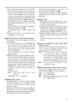
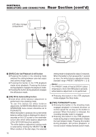
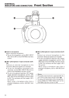
CONTROLS, INDICATORS AND CONNECTORS Front Section ] \ ` \ Built-in microphone Built-in monaural microphone. ● To use this microphone, set the MIC1 INPUT SEL item to INT on the SYSTEM [1/2] menu screen. ] [MIC 1] Microphone 1 input connector (XLR3P) Connect an external microphone to this connector. Monaural signals are recorded. ● To use the microphone connected to this connector, set the MIC1 INPUT SEL item to XLR on the SYSTEM [1/2] menu screen. ● To use a microphone requiring +48 V power supply (phantom microphone), set the +48V MIC1 item on the SYSTEM [1/2] menu screen to ON. This connector will then supply +48 V DC current. When using a microphone other than a phantom microphone, set the +48V MIC1 item to OFF. ` [MIC 2] Microphone 2 input connector (XLR3P) Connect an external microphone to this connector. Monaural signals are recorded. ● To use a microphone requiring +48 V power supply (phantom microphone), set the +48V MIC2 item on the SYSTEM [1/2] menu screen to ON. This connector will then supply +48 V DC current. When using a microphone other than a phantom microphone, set the +48V MIC2 item to OFF. Memo: • The audio input channel is selected with the CH-1/CH-2 audio input selector switch M. • To reduce the wind noise of the microphone, set the WIND CUT MIC1/MIC2 item on the SYSTEM [1/2] menu screen to ON. 20
-
 1
1 -
2
-
3
-
4
-
5
-
6
-
7
-
8
-
9
-
10
-
11
-
12
-
13
-
14
-
 15
15 -
 16
16 -
 17
17 -
 18
18 -
 19
19 -
 20
20 -
 21
21 -
 22
22 -
 23
23 -
 24
24 -
 25
25 -
26
-
27
-
28
-
29
-
30
-
31
-
32
-
33
-
34
-
35
-
36
-
37
-
38
-
39
-
40
-
41
-
42
-
43
-
44
-
45
-
46
-
47
-
48
-
49
-
50
-
51
-
52
-
53
-
54
-
55
-
56
-
57
-
58
-
59
-
60
-
61
-
62
-
63
-
64
-
65
-
66
-
67
-
68
-
69
-
70
-
71
-
72
-
73
-
74
-
75
-
76
-
77
-
78
-
79
-
80
-
81
-
82
-
83
-
84
-
85
-
86
-
87
-
88
-
89
-
90
-
91
-
92
-
93
-
94
-
95
-
96
-
97
-
98
-
99
-
100
-
101
-
102
-
103
-
104
-
105
-
106
-
107
-
108
 |
 |
