JVC GY-DV300U 108 pg. instruction manual on the GY-DV300U Pro-DV Camcorder (PD - Page 28
Contents
 |
View all JVC GY-DV300U manuals
Add to My Manuals
Save this manual to your list of manuals |
Page 28 highlights
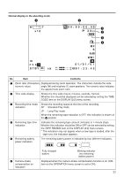
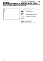
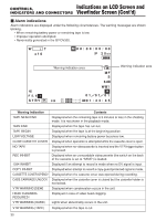
CONTROLS, Indications on LCD Screen and INDICATORS AND CONNECTORS Viewfinder Screen (Cont'd) VOL. P L AY DV y ui o !0 No. Item 6 VTR mode indication 7 DV signal indication 8 Audio sampling frequency indication 9 Audio level meters display 0 Date and time indication Contents Indicates status of VTR operation. (STOP, PLAY, FF, REW, EJECT, STBY, FWD, REV, BSRH) DV : Displayed when IEEE1394 signal is recorded from the DV connector. The audio sampling frequency by which the recording was made is displayed during playback. (32K, 48K, 44.1K) The playback audio level meters are displayed during playback. These are not shown when the AUDIO LEVEL item is set to OFF on the DISPLAY [2/2] menu screen. Recorded data is show during playback, fast forward and rewind operations. During recording, the data from the DV connector is shown. The current data is shown in the stop mode. The indication is enabled/disabled by selecting the TIME/DATE item on the DISPLAY [2/2] menu screen. The display style is selected by setting the DISP STYLE item. When the date and time are not set, the indication will be as follows 28
-
 1
1 -
2
-
3
-
4
-
5
-
6
-
7
-
8
-
9
-
10
-
11
-
12
-
13
-
14
-
15
-
16
-
17
-
18
-
19
-
20
-
21
-
22
-
 23
23 -
 24
24 -
 25
25 -
 26
26 -
 27
27 -
 28
28 -
 29
29 -
 30
30 -
 31
31 -
 32
32 -
 33
33 -
34
-
35
-
36
-
37
-
38
-
39
-
40
-
41
-
42
-
43
-
44
-
45
-
46
-
47
-
48
-
49
-
50
-
51
-
52
-
53
-
54
-
55
-
56
-
57
-
58
-
59
-
60
-
61
-
62
-
63
-
64
-
65
-
66
-
67
-
68
-
69
-
70
-
71
-
72
-
73
-
74
-
75
-
76
-
77
-
78
-
79
-
80
-
81
-
82
-
83
-
84
-
85
-
86
-
87
-
88
-
89
-
90
-
91
-
92
-
93
-
94
-
95
-
96
-
97
-
98
-
99
-
100
-
101
-
102
-
103
-
104
-
105
-
106
-
107
-
108
 |
 |
