Kyocera 1010N Operation Guide - Page 21
Remote Operation Panel, The explanations of messages appearing in this manual are based
 |
UPC - 632983001004
View all Kyocera 1010N manuals
Add to My Manuals
Save this manual to your list of manuals |
Page 21 highlights
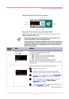
KM-NET Remote Operation Panel Utility Remote Operation Panel Start-up Screen 67 1 2 8 Reference Number 1 2 Note Name 34 5 Functions of the Remote Operation Panel Utility The following table explains the names and function of the parts of the Remote Operation Panel utility. • The numbers appearing in the figure above are referred to in the 'Reference Number' column of the table below. • The explanations of messages appearing in this manual are based on the premise that the printer is used over a network. Accordingly, the explanations include some messages that do not appear when the printer is used locally. Function Message display (1) (3)(4) (2) The printer status is displayed on the upper line (1) and the following information is displayed on the lower lines. (2) Active interface PAR: Standard bi-directional parallel interface SER: Optional serial interface (RS-232C/422A) OPT: Optional network interface (3) Paper size of the currently selected paper cassette (4) Paper type of the currently selected paper cassette When an error occurs, details of the error are displayed on the upper and lower lines. Displays a suitable icon according to the printer's status. : The printer is ready to print. : The paper is exhausted or the cassette is not installed properly. Load more paper or close the cassette properly. : A paper jam has occurred. Refer to section 4.4 Correcting a Paper Jam on page 4-14 and remove the jammed paper. : Toner is running low or is exhausted. Replace with a new toner container. See section 3.1 Toner Container Replacement on page 3-2. : An error has occurred. Refer to the message displayed. See section 4.3 Indicators on page 4-5. (Continued on next page) 1-10
-
 1
1 -
2
-
3
-
4
-
5
-
6
-
7
-
8
-
9
-
10
-
11
-
12
-
13
-
14
-
15
-
 16
16 -
 17
17 -
 18
18 -
 19
19 -
 20
20 -
 21
21 -
 22
22 -
 23
23 -
 24
24 -
 25
25 -
 26
26 -
27
-
28
-
29
-
30
-
31
-
32
-
33
-
34
-
35
-
36
-
37
-
38
-
39
-
40
-
41
-
42
-
43
-
44
-
45
-
46
-
47
-
48
-
49
-
50
-
51
-
52
-
53
-
54
-
55
-
56
-
57
-
58
-
59
-
60
-
61
-
62
-
63
-
64
-
65
-
66
-
67
-
68
-
69
-
70
-
71
-
72
-
73
-
74
-
75
-
76
-
77
-
78
-
79
-
80
-
81
-
82
-
83
-
84
-
85
-
86
-
87
-
88
-
89
-
90
-
91
-
92
-
93
-
94
-
95
-
96
-
97
-
98
-
99
-
100
-
101
-
102
-
103
-
104
-
105
-
106
-
107
-
108
-
109
-
110
-
111
-
112
-
113
-
114
-
115
-
116
-
117
-
118
-
119
-
120
-
121
-
122
-
123
-
124
-
125
-
126
-
127
-
128
-
129
-
130
-
131
-
132
-
133
-
134
-
135
-
136
-
137
-
138
-
139
-
140
-
141
-
142
-
143
-
144
-
145
-
146
-
147
-
148
-
149
-
150
-
151
-
152
-
153
-
154
-
155
-
156
-
157
-
158
-
159
-
160
-
161
-
162
-
163
-
164
-
165
-
166
-
167
-
168
-
169
-
170
-
171
-
172
-
173
-
174
-
175
-
176
-
177
-
178
-
179
-
180
-
181
-
182
 |
 |
