Kyocera KM-C2030 Fiery X3e Configuration Guide for Ver 2.0 - Page 16
Quick path to installation
 |
View all Kyocera KM-C2030 manuals
Add to My Manuals
Save this manual to your list of manuals |
Page 16 highlights
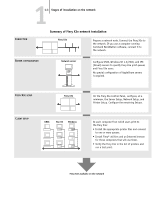
11-4 Connecting to the Network Quick path to installation The diagrams on the following pages show typical systems you can use to print and run Fiery software from remote workstations. Find the page with your preferred platform and network type, and then look up the setup procedures referenced in the "Key to setup" in the upper-left corner of each diagram. The diagrams describe devices that use the supported networking protocols. They are logical diagrams and are not intended to describe the physical arrangement (topology) of devices on the network. A variety of physical arrangements is possible with each logical arrangement. For example, twisted pair Ethernet networks commonly use a star configuration around a hub, rather than a bus arrangement. The design of physical networks is beyond the scope of this manual. If your network uses more than one protocol or more than one type of workstation, combine the setups listed for each component of your system. Multiple protocols (shown in the diagrams as parallel lines) can run on the same cable. A solid connection from the Fiery X3e with an arrow indicates that other supported network types can be operational at the same time. The protocols used in these diagrams are indicated as follows: IPX (Novell) AppleTalk TCP/IP (lpd, nbt, or http) Parallel Other
-
 1
1 -
2
-
3
-
4
-
5
-
6
-
7
-
8
-
9
-
10
-
 11
11 -
 12
12 -
 13
13 -
 14
14 -
 15
15 -
 16
16 -
 17
17 -
 18
18 -
 19
19 -
 20
20 -
 21
21 -
22
-
23
-
24
-
25
-
26
-
27
-
28
-
29
-
30
-
31
-
32
-
33
-
34
-
35
-
36
-
37
-
38
-
39
-
40
-
41
-
42
-
43
-
44
-
45
-
46
-
47
-
48
-
49
-
50
-
51
-
52
-
53
-
54
-
55
-
56
-
57
-
58
-
59
-
60
-
61
-
62
-
63
-
64
-
65
-
66
-
67
-
68
-
69
-
70
-
71
-
72
-
73
-
74
-
75
-
76
-
77
-
78
-
79
-
80
-
81
-
82
-
83
-
84
-
85
-
86
-
87
-
88
-
89
-
90
-
91
-
92
-
93
-
94
-
95
-
96
-
97
-
98
-
99
-
100
-
101
-
102
-
103
-
104
-
105
-
106
-
107
-
108
-
109
-
110
-
111
-
112
-
113
-
114
-
115
-
116
-
117
-
118
-
119
-
120
-
121
-
122
-
123
-
124
-
125
-
126
-
127
-
128
-
129
-
130
-
131
-
132
-
133
-
134
-
135
-
136
-
137
-
138
-
139
-
140
-
141
-
142
-
143
-
144
-
145
-
146
-
147
-
148
-
149
-
150
-
151
-
152
-
153
-
154
-
155
-
156
-
157
-
158
-
159
-
160
-
161
-
162
-
163
-
164
-
165
-
166
-
167
-
168
-
169
-
170
-
171
-
172
-
173
-
174
 |
 |
