Panasonic AG-DVX200 Operating Instructions - Volume 2 - Page 67
Using an external microphone or audio equipment, Table of audio input patterns
 |
View all Panasonic AG-DVX200 manuals
Add to My Manuals
Save this manual to your list of manuals |
Page 67 highlights
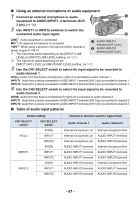
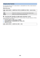
∫ Using an external microphone or audio equipment 1 Connect an external microphone or audio equipment to AUDIO INPUT1, 2 terminals (XLR 3 pin). (l 14) 2 Use INPUT1 or INPUT2 switches to switch the connected audio input signal. LINE*1: Audio equipment is connected MIC*2: An external microphone is connected +48V*2: When using a phantom microphone (which requires a power supply of +48 V) *1 The input level varies depending on the [INPUT1 LINE A AUDIO INPUT1 terminal (XLR 3 pin) B AUDIO INPUT2 terminal (XLR 3 pin) LEVEL] or [INPUT2 LINE LEVEL] setting. (l 167) *2 The input level varies depending on the [INPUT1 MIC LEVEL] or [INPUT2 MIC LEVEL] setting. (l 167) 3 Use the CH1 SELECT switch to select the input signal to be recorded to audio channel 1. INT(L): Audio from the built-in microphone L (left) ch is recorded to audio channel 1. INPUT1: Audio from a device connected to AUDIO INPUT1 terminal (XLR 3 pin) is recorded to channel 1. INPUT2: Audio from a device connected to AUDIO INPUT2 terminal (XLR 3 pin) is recorded to channel 1. 4 Use the CH2 SELECT switch to select the input signal to be recorded to audio channel 2. INT(R): Audio from the built-in microphone R (right) ch is recorded to audio channel 2. INPUT1: Audio from a device connected to AUDIO INPUT1 terminal (XLR 3 pin) is recorded to channel 2. INPUT2: Audio from a device connected to AUDIO INPUT2 terminal (XLR 3 pin) is recorded to channel 2. ∫ Table of audio input patterns Switch setting CH1 SELECT switch CH2 SELECT switch INT(R) INT(L) INPUT1 INPUT2 INT(R) INPUT1 INPUT1 INPUT2 INT(R) INPUT2 INPUT1 INPUT2 Channel or terminal used for signal input Audio channel 1 Audio channel 2 Internal microphone Lch Internal microphone Lch Internal microphone Lch AUDIO INPUT1 terminal AUDIO INPUT1 terminal AUDIO INPUT1 terminal AUDIO INPUT2 terminal AUDIO INPUT2 terminal AUDIO INPUT2 terminal Internal microphone Rch AUDIO INPUT1 terminal AUDIO INPUT2 terminal Internal microphone Rch AUDIO INPUT1 terminal AUDIO INPUT2 terminal Internal microphone Rch AUDIO INPUT1 terminal AUDIO INPUT2 terminal - 67 -
-
 1
1 -
2
-
3
-
4
-
5
-
6
-
7
-
8
-
9
-
10
-
11
-
12
-
13
-
14
-
15
-
16
-
17
-
18
-
19
-
20
-
21
-
22
-
23
-
24
-
25
-
26
-
27
-
28
-
29
-
30
-
31
-
32
-
33
-
34
-
35
-
36
-
37
-
38
-
39
-
40
-
41
-
42
-
43
-
44
-
45
-
46
-
47
-
48
-
49
-
50
-
51
-
52
-
53
-
54
-
55
-
56
-
57
-
58
-
59
-
60
-
61
-
 62
62 -
 63
63 -
 64
64 -
 65
65 -
 66
66 -
 67
67 -
 68
68 -
 69
69 -
 70
70 -
 71
71 -
 72
72 -
73
-
74
-
75
-
76
-
77
-
78
-
79
-
80
-
81
-
82
-
83
-
84
-
85
-
86
-
87
-
88
-
89
-
90
-
91
-
92
-
93
-
94
-
95
-
96
-
97
-
98
-
99
-
100
-
101
-
102
-
103
-
104
-
105
-
106
-
107
-
108
-
109
-
110
-
111
-
112
-
113
-
114
-
115
-
116
-
117
-
118
-
119
-
120
-
121
-
122
-
123
-
124
-
125
-
126
-
127
-
128
-
129
-
130
-
131
-
132
-
133
-
134
-
135
-
136
-
137
-
138
-
139
-
140
-
141
-
142
-
143
-
144
-
145
-
146
-
147
-
148
-
149
-
150
-
151
-
152
-
153
-
154
-
155
-
156
-
157
-
158
-
159
-
160
-
161
-
162
-
163
-
164
-
165
-
166
-
167
-
168
-
169
-
170
-
171
-
172
-
173
-
174
-
175
-
176
-
177
-
178
-
179
-
180
-
181
-
182
-
183
-
184
-
185
-
186
-
187
-
188
-
189
-
190
-
191
-
192
-
193
-
194
-
195
-
196
-
197
-
198
-
199
-
200
-
201
-
202
-
203
 |
 |
