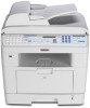
Ricoh AC205 Service Manual
Ricoh AC205 Manual
 |
View all Ricoh AC205 manuals
Add to My Manuals
Save this manual to your list of manuals |
Ricoh AC205 manual content summary:
- Ricoh AC205 | Service Manual - Page 1
B273 SERVICE MANUAL 002544MIU - Ricoh AC205 | Service Manual - Page 2
- Ricoh AC205 | Service Manual - Page 3
B273 SERVICE MANUAL - Ricoh AC205 | Service Manual - Page 4
- Ricoh AC205 | Service Manual - Page 5
B273 SERVICE MANUAL 002544MIU - Ricoh AC205 | Service Manual - Page 6
- Ricoh AC205 | Service Manual - Page 7
responsibility when discussing the information contained within this document to maintain a level of confidentiality that is in the best interest of Ricoh Corporation and its member companies. NO PART OF THIS DOCUMENT MAY BE REPRODUCED IN ANY FASHION AND DISTRIBUTED WITHOUT THE PRIOR PERMISSION OF - Ricoh AC205 | Service Manual - Page 8
- Ricoh AC205 | Service Manual - Page 9
WARNING The Service Manual contains information regarding service techniques, procedures, processes and spare parts of office equipment distributed by Ricoh Corporation. Users of this manual should be either service trained or certified by successfully completing a Ricoh Technical Training Program. - Ricoh AC205 | Service Manual - Page 10
- Ricoh AC205 | Service Manual - Page 11
LEGEND PRODUCT CODE B273 GESTETNER DSm520pf COMPANY LANIER AC122 RICOH AC205 SAVIN AC205 DOCUMENTATION HISTORY REV. NO. * DATE 09/2005 COMMENTS Original Printing - Ricoh AC205 | Service Manual - Page 12
- Ricoh AC205 | Service Manual - Page 13
B273 TABLE OF CONTENTS INSTALLATION 1. INSTALLATION 1-1 PREVENTIVE MAINTENANCE 2. PREVENTIVE MAINTENANCE 2-1 2.1 PM INTERVALS 2-1 REPLACEMENT AND ADJUSTMENT 3. REPLACEMENT AND ADJUSTMENT 3-1 3.1 GENERAL PRECAUTIONS 3-1 3.1.1 SERVICING THE MACHINE 3-1 3.1.2 RELEASING PLASTIC LATCHES 3-1 3.2 - Ricoh AC205 | Service Manual - Page 14
3-47 Paper Feed Unit Pick-up Roller 3-48 TROUBLESHOOTING 4. TROUBLESHOOTING 4-1 4.1 PAPER PATH 4-1 4.1.1 COPY/SCAN DOCUMENT PATH 4-2 Scanner 4-2 Engine 4-3 4.1.2 PRINTER PAPER PATH 4-4 4.2 PAPER JAM CONDITIONS 4-5 Jam0 (Paper Feed Area) Jam1 (Fusing/Toner Cartridge 4-5 Jam2 (Paper Exit Area - Ricoh AC205 | Service Manual - Page 15
POOR QUALITY OF SCANNED IMAGES 4-32 4.9 ERROR MESSAGES 4-33 4.10 TONER CARTRIDGE 4-36 4.10.1 TONER CARTRIDGE PRECAUTIONS 4-36 4.10.2 REDISTRIBUTING TONER 4-37 4.10.3 TONER CARTRIDGE ERROR MESSAGES 4-38 4.10.4 TONER CARTRIDE DETAILS 4-39 4.11 SOFTWARE PROBLEMS 4-43 4.11.1 PRINTER DOES NOT - Ricoh AC205 | Service Manual - Page 16
4.12.3 SYNCTHRU INSTALLATION PROBLEMS 4-48 SERVICE PROGRAM MODE 5. SERVICE PROGRAM MODE 5-1 5.1 TECH MODE 5-1 5.1.1 HOW TO ENTER TECH AND EXIT MODE 5-1 What you can do in Tech Mode 5-1 5.1.2 DATA SET-UP 5-2 Send Level 5-2 Dial Mode 5-2 Modem Speed 5-2 Error Rate 5-2 Notify Toner 5-2 CLEAR - Ricoh AC205 | Service Manual - Page 17
ASSEMBLY 6-4 Thermostat 6-4 Thermistor 6-4 Hot Roller 6-4 Pressure Roller 6-4 Safety Features 6-4 Safety Devices 6-4 6.2.5 SCANNING UNIT 6-5 CCD Module Specifications 6-5 6.2.6 LASER SCANNING UNIT (LSU 6-5 6.2.7 TONER CARTRIDGE 6-6 6.2.8 NEW AIO DETECTION 6-7 6.2.9 TONER END DETECTION - Ricoh AC205 | Service Manual - Page 18
6-16 6.5 ENGINE 6-17 6.5.1 PAPER FEED 6-17 Jam0 (feed area 6-17 Jam1 (inside the machine 6-17 Jam2 (exit area 6-17 6.5.2 DRIVE 6-18 6.5.3 TRANSFER 6-18 6.5.4 FUSING 6-18 6.5.5 LASER SCANNING UNIT 6-19 6.6 OPERATION PANEL (OPE 6-19 6.7 USB HOST 6-20 6.8 FAX SECTION 6-20 6.8.1 MODEM 6-20 - Ricoh AC205 | Service Manual - Page 19
to be hazardous. The laser system and printer are designed to prevent access to laser radiation during normal operation, user maintenance, or prescribed service activities. Never operate or service the printer with the protective cover removed from Laser/Scanner assembly. The reflected beam - Ricoh AC205 | Service Manual - Page 20
the toner cartridge may be harmful if swallowed. Contact a doctor immediately if toner powder is swallowed. ELECTRIC SHOCK AND FIRE SAFETY PRECAUTIONS Failure to adhere to the following instructions could cause electric shock or cause a fire. 1. Use only the specified voltage to power this machine - Ricoh AC205 | Service Manual - Page 21
shock. HANDLING PRECAUTIONS The following instructions are for your own personal safety, to avoid injury and to prevent damage to the machine. 1. Ensure that the machine is installed on a level surface, capable of supporting its weight. Failure to do so could cause the machine to tip or fall - Ricoh AC205 | Service Manual - Page 22
rating are correct. CAUTION1.TIF 5. When removing or re-fitting any parts, do not use excessive force (especially when fitting screws into plastic). 6. Take care not to drop any small parts into the machine. 7. Handling of the OPC Drum: • The OPC Drum can be damaged if it is exposed to - Ricoh AC205 | Service Manual - Page 23
propelled chemicals. When sprayed, these can generate electrical charges sufficient to damage ESDs. 6. Do not remove a replacement ESD from its protective packaging until immediately before installing it. Most replacement ESDs are packaged with all leads shorted together by conductive foam, aluminum - Ricoh AC205 | Service Manual - Page 24
- Ricoh AC205 | Service Manual - Page 25
TA B POSITION 1 TA B POSITION 2 TA B POSITION 3 TA B POSITION 4 INSTALLATION PREVENTIVE MAINTENANCE REPLACEMENT AND ADJUSTMENT TROUBLESHOOTING SERVICE PROGRAM MODE DETAILED DESCRIPTIONS SPECIFICATIONS APPENDIX TA B POSITION 5 TA B POSITION 6 TA B POSITION 7 TA B POSITION 8 - Ricoh AC205 | Service Manual - Page 26
- Ricoh AC205 | Service Manual - Page 27
INSTALLATION - Ricoh AC205 | Service Manual - Page 28
- Ricoh AC205 | Service Manual - Page 29
1. INSTALLATION Refer to the Operating Instructions for Installation procedures. INSTALLATION Installation SM 1-1 B273 - Ricoh AC205 | Service Manual - Page 30
- Ricoh AC205 | Service Manual - Page 31
PREVENTIVE MAINTENANCE - Ricoh AC205 | Service Manual - Page 32
- Ricoh AC205 | Service Manual - Page 33
. It is expected that the intervals indicated below will exceed machine life. However, if the indicated interval is reached, replace the component. Component Scanner Printer ADF Rubber Pad ADF Pick-up Ass'y Pick-up Ass'y Transfer Roller Fusing Unit Replacement Cycle 20,000 Pages 80,000 Pages 150 - Ricoh AC205 | Service Manual - Page 34
- Ricoh AC205 | Service Manual - Page 35
REPLACEMENT AND ADJUSTMENT - Ricoh AC205 | Service Manual - Page 36
- Ricoh AC205 | Service Manual - Page 37
stored in memory before you service the machine. 2. Remove the toner cartridge before you disassemble parts. 3. Unplug the power cord before you service the machine. 4. Use a flat clean surface to service the machine. 5. Use only approved replacement parts. Machine function cannot be guaranteed if - Ricoh AC205 | Service Manual - Page 38
COVERS 3.2 COVERS 3.2.1 REAR COVER [A] B273R902.WMF B273R903.WMF 1. Remove 4 x securing the rear cover [A]. Remove the rear cover from the frame assembly. [B] B273R904.WMF 2. Unhook the face cover [B] from the rear cover as shown above. Lift the face cover out. B273 3-2 SM - Ricoh AC205 | Service Manual - Page 39
the paper tray unit before removing the side covers. Right Cover COVERS Replacement Adjustment [B] [A] B273R905.WMF 1. Open the front cover and remove 2 x on the front, and 1 x on the back. 2. Release 3 x clips [A] underneath the cover. 3. Ease the rear screw bracket over its location pin - Ricoh AC205 | Service Manual - Page 40
COVERS Left Cover [B] [A] B273R906.WMF 1. Release 3 x clips [A] underneath the cover. 2. Ease the rear screw bracket over its location pin and gently slide the left cover [B] to the right. 3. Remove the left cover from the frame. B273 3-4 SM - Ricoh AC205 | Service Manual - Page 41
3.2.3 FRONT COVER COVERS Replacement Adjustment [A] [B] B273R907.WMF 1. Open the front cover [A] and remove the toner cartridge [B]. B273R908.WMF [A] B273R909.WMF 2. Unhook the front cover [A] from the frame assembly. Remove the front cover as shown above. SM 3-5 B273 - Ricoh AC205 | Service Manual - Page 42
SCANNER ASSEMBLY 3.3 SCANNER ASSEMBLY Remove the following before removing the ADF motor assembly: Rear cover 3.2.1 Side covers 3.2.2 1. Remove 2 x from the scanner assembly, as shown. [A] [B] 2. Remove 5 x [A], as shown. 3. Remove the ground wire screw [B]. B273R910.WMF B273 3-6 - Ricoh AC205 | Service Manual - Page 43
SCANNER ASSEMBLY [C] Replacement Adjustment 4. Lift up the scanner assembly, as shown above. B273R912.WMF [D] 5. Lift and remove the platen cover [D], 1 as shown. 3 2 B273R913.WMF SM 3-7 B273 - Ricoh AC205 | Service Manual - Page 44
[F] [E] B273R914.WMF 6. Free the scanner cable harness [E] from the clips [F] underneath the scanner. Remove it from the frame. [G] B273R915.WMF 7. Lift the front part of the OPE front cover [G] to release it from the hooks connecting it to the scanning assembly. Remove the OPE front cover. B273 - Ricoh AC205 | Service Manual - Page 45
the harness is threaded through the frame. [J] B273R917.WMF 9. Remove 4 x securing the upper part [J] of the scanning unit. 10. Unclip 2 x clip securing the upper part of the scanning unit from the scanner assembly. Lift the upper part of the scanning unit upward and remove it. SM 3-9 B273 - Ricoh AC205 | Service Manual - Page 46
SCANNER ASSEMBLY [K] 11. Remove the CCD cable [K], as shown above. [M] B273R918.WMF [L] B273R919.WMF 12. Pull up the CCD shaft [L] and remove the scanner module [M]. B273 3-10 SM - Ricoh AC205 | Service Manual - Page 47
SCANNER ASSEMBLY [N] [O] Replacement Adjustment B273R920.WMF 13. Squeeze the spring [N] to relieve tension on the belt [O]. Lift the belt away from the pulleys as shown. [P] [Q] [R] B273R921.WMF 14. Remove the reduction gear [P] and idle gear [Q], as shown. 15. Remove 3 x and remove the motor - Ricoh AC205 | Service Manual - Page 48
SCANNER ASSEMBLY [S] B273R922.WMF 16. Unplug the connector from the open sensor assembly [S]. Open Sensor [T] 17. Unlatch the cover open sensor [T] and remove it. B273R980.WMF B273 3-12 SM - Ricoh AC205 | Service Manual - Page 49
SCANNER ASSEMBLY Lock Unlock 18. Remove the CCD lock [U]. [U] B273R923.WMF Replacement Adjustment SM 3-13 B273 - Ricoh AC205 | Service Manual - Page 50
SCANNER ASSEMBLY 3.3.1 REASSEMBLING THE SCANNER ASSEMBLY [A] B273R924.WMF Ensure that the tension spring [A] is as close to the right-hand side of the scanner assembly as possible when reassembling the scanner module, belt, and belt spring. B273 3-14 SM - Ricoh AC205 | Service Manual - Page 51
the ADF motor assembly: Rear cover 3.2.1 Side covers .3.2.2 Scanner assembly 3.3 [A] [B] Replacement Adjustment B273R925.WMF 1. Unclip the harness [A] from the platen cover. 2. Remove the 2 x securing the ADF assembly and remove it. (Ensure that the harness is threaded through the frames - Ricoh AC205 | Service Manual - Page 52
B273R927.WMF 4. Release the bushing [D] and rotate it until it reaches the slot, as shown above. 5. Remove the pick-up assembly [E]. [F] B273R928.WMF 6. Remove the 2 x securing the upper cover [F] and remove the upper cover, as shown above. NOTE: Note the position of the ferrite core and motor - Ricoh AC205 | Service Manual - Page 53
In these cases, perform the following: 1) Open the ADF cover and remove the pick-up assembly. 2) Using a pair of tweezers or a small flat-bladed screwdriver, release the clips on both sides of the ADF separator pad assembly. 3) Remove the ADF separator pad assembly from the machine. SM 3-17 B273 - Ricoh AC205 | Service Manual - Page 54
the operation panel: Rear cover 3.2.1 Side covers 3.2.2 Scanner assembly 3.3 [A] [B] [C] B273R931.WMF B273R930.WMF 1. Remove 10 x securing the operation board panel cover [A] from the operation board panel assembly [B]. 2. Remove the contact rubber [C] from the operation board panel - Ricoh AC205 | Service Manual - Page 55
OPERATION PANEL [D] B273R932.WMF 3. Remove the keypad [D] from the operation panel board cover. Replacement Adjustment SM 3-19 B273 - Ricoh AC205 | Service Manual - Page 56
MIDDLE COVER AND EXIT ROLLER 3.6 MIDDLE COVER AND EXIT ROLLER Remove the following before removing the middle cover and exit roller: Rear cover 3.2.1 Side covers 3.2.2 Scanner assembly 3.3 [A] B273R933.WMF 1. Remove 4 x securing the middle cover [A]. Remove the middle cover. [B] [A] - Ricoh AC205 | Service Manual - Page 57
MIDDLE COVER AND EXIT ROLLER [C] [D] [E] B273R935.WMF 5. Remove the exit gear [C], exit roller [D], and 4 x bushings [E], as shown above. Replacement Adjustment SM 3-21 B273 - Ricoh AC205 | Service Manual - Page 58
the control shield assembly: Rear cover 3.2.1 Side covers 3.2.2 [A] B273R936.WMF 1. Remove all connectors and 5 x securing the controller shield assembly [A] to the middle cover and the frame. Remove the assembly. 2. Remove 2 x connecting the NIC card [B] to the controller board assembly - Ricoh AC205 | Service Manual - Page 59
Replacement Adjustment CONTROLLER SHIELD ASSEMBLY [D] [C] B273R938.WMF 4. Remove the 5 x to remove the bracket [C] from the main board [D]. SM 3-23 B273 - Ricoh AC205 | Service Manual - Page 60
ASSEMBLY AND EXIT BOARD 3.8 ENGINE SHIELD ASSEMBLY AND EXIT BOARD Remove the following before removing the engine shield and exit board: Rear cover 3.2.1 Side covers 3.2.2 Scanner assembly 3.3 3.8.1 ENGINE SHIELD [A] [C] [B] 1. Unplug the following connectors: [A] Exit connector [B] Main - Ricoh AC205 | Service Manual - Page 61
ENGINE SHIELD ASSEMBLY AND EXIT BOARD [A] B273R940.WMF 2. Remove the 11 x securing the engine shield assembly [A]. Tilt the assembly to one side. Unplug all harnesses before removing the assembly. Replacement Adjustment SM 3-25 B273 - Ricoh AC205 | Service Manual - Page 62
ENGINE SHIELD ASSEMBLY AND EXIT BOARD 3.8.2 EXIT BOARD 1. Remove the 2 x exit board [B] 2. Remove the board. [B] B273R941.WMF B273 3-26 SM - Ricoh AC205 | Service Manual - Page 63
SMPS and LIU: Rear cover 3.2.1 Side covers 3.2.2 Scanner assembly 3.3 Engine shield assembly 3.8 SMPS AND LIU [A] Replacement Adjustment B273R942.WMF 1. Remove the 2 x securing the inlet bracket [A] and remove the bracket. 2. Remove the 1 x [B] securing the engine shield ground - Ricoh AC205 | Service Manual - Page 64
SMPS AND LIU [C] B273R944.WMF 3. Remove the 3 x securing the SMPS [C]. Lift the SMPS out as shown above. 4. Remove the 3 x securing the LIU. Lift the LIU [D] out, as shown in the illustration on the right. [D] B273 3-28 B273R945.WMF SM - Ricoh AC205 | Service Manual - Page 65
FUSING UNIT 3.10 FUSING UNIT Remove the following before removing the fusing unit: Rear cover 3.2.1 3.10.1 FUSING UNIT ASSEMBLY NOTE: Perform procedure 3.10.1 only if removal of entire fusing unit assembly is required. Otherwise, use individual component procedures. [A] Replacement Adjustment - Ricoh AC205 | Service Manual - Page 66
(bolts) [A] securing the thermostat [B]. 2. Lift the thermostat [B] out. Ensure that bolts and nuts [C] are stored in a safe place. 3.10.3 FUSING LAMP [B] [A] 1. Remove the 2 x securing the fusing lamp [A]. B273R948.WMF 2. Remove the fusing lamp [A] from the hot roller [B]. B273 3-30 SM - Ricoh AC205 | Service Manual - Page 67
Replacement Adjustment 3.10.4 STRIPPER PAWLS FUSING UNIT [C] [A] [B] 1. Remove the 4 x securing the fusing unit cover [A]. 2. Remove the 2 x securing the guide input [B]. B273R949.WMF 3. Remove the stripper pawls [C] from the fusing unit cover [A]. SM 3-31 B273 - Ricoh AC205 | Service Manual - Page 68
pawl holder slots (shown in white circles below). [A] B273R950.TIF 2. Place the top part of the fusing unit onto the bottom part of the fusing unit. 3. Place the four stripper pawls [A] back into the stripper of the fusing unit and place it back into the machine. [A] B273 3-32 B273R951.TIF SM - Ricoh AC205 | Service Manual - Page 69
position. Note that the stripper pawls are not correctly set into the stripper pawl holder slots. Do not place the fusing unit back into the machine with the stripper pawls in the wrong position. Replacement Adjustment B273R952.TIF SM 3-33 B273 - Ricoh AC205 | Service Manual - Page 70
FUSING UNIT 3.10.5 THERMISTOR [A] B273R950.WMF 1. Unwrap the thermistor harness [A], as shown above. [B] B273R951.WMF 2. Remove 1 x securing the thermistor [B] and remove the thermistor. B273 3-34 SM - Ricoh AC205 | Service Manual - Page 71
Replacement Adjustment FAN 3.11 FAN Remove the following before removing the fan: Rear cover 3.2.1 Side covers 3.2.2 [B] 1. Unplug the 1 x [A] from the SMPS. 2. Remove the 1 x securing fan [B]. 3. Remove the fan [B]. [A] B273R952.WMF SM 3-35 B273 - Ricoh AC205 | Service Manual - Page 72
LSU 3.12 LSU Remove the following before removing the LSU: Rear cover 3.2.1 Side covers 3.2.2 Scanner assembly 3.3 Front cover 3.2.3 Middle cover 3.6 [A] [B] B273R953.WMF 1. Remove the 4 x securing the LSU [A] and remove the LSU. 2. Ensure that the wire [B] is kept in a safe place. 3. - Ricoh AC205 | Service Manual - Page 73
CRUM BOARD 3.13 CRUM BOARD Remove the following before removing the CRUM board: Rear cover 3.2.1 Side covers 3.2.2 Scanner assembly 3.3 Front cover 3.2.3 Middle cover 3.6 LSU 3.12 [A] Replacement Adjustment B273R956.WMF 1. Remove the 4 x to separate the CRUM board [A] from the - Ricoh AC205 | Service Manual - Page 74
covers 3.2.2 Controller shield assembly 3.7 [A] 1. Remove the 5 x securing the drive assembly. [B] 2. Remove the drive assembly [B]. 3. Unplug the reassembling the drive assembly. It is necessary to consider only screws one to five at the time of drive assembly replacement. Screw number six - Ricoh AC205 | Service Manual - Page 75
cover mid-front: Rear cover 3.2.1 Side covers 3.2.2 Middle cover 3.6 COVER MID-FRONT [B] [A] 1. Remove the 4 x securing the cover mid-front [A]. 2. Release the 2 clips [B] in the center. 3. Remove the cover mid-front [A]. B273R958.WMF NOTE: The cover is very fragile. Use caution when - Ricoh AC205 | Service Manual - Page 76
the transfer assembly: Rear cover 3.2.1 Side covers 3.2.2 Scanner assembly 3.3 Front cover 3.2.3 Middle cover 3.6 LSU 3.12 Cover Mid-Front 3.15 [A] B273R959.WMF 1. Remove the 3 x securing the transfer ground [A] and remove the ground. [C] [B] [D] B273R960.WMF 2. Unplug the Pre - Ricoh AC205 | Service Manual - Page 77
TRANSFER ASSEMBLY [E] [F] B273R961.WMF 4. Remove the transfer roller [E] by pressing the hook [F] securing the roller to the right. [H] [G] Replacement Adjustment 5. Unlatch the bushing [G] and remove it. 6. Lift the transfer roller [H] out, as shown above. B273R962.WMF SM 3-41 B273 - Ricoh AC205 | Service Manual - Page 78
3.2.2 Scanner assembly 3.3 Front cover 3.2.3 Middle cover 3.6 Controller shield assembly 3.7 Drive assembly 3.14 [A] B273R963.WMF 1. Remove the 4 x securing the guide paper front, and remove the guide paper. 2. Remove the 2 x on [B] both sides of the guide paper, to remove the - Ricoh AC205 | Service Manual - Page 79
FEED ASSEMBLY [C] Replacement Adjustment B273R965.WMF 4. Remove the 3 x securing the feed bracket [C], and remove the bracket. [D] 5. Remove feed gear 2 [D]. B273R967.WMF SM 3-43 B273 - Ricoh AC205 | Service Manual - Page 80
FEED ASSEMBLY [E] 6. Remove feed gear 1 [E]. [F] B273R966.WMF [G] 7. Remove the feed roller [F]. 8. Remove feed roller 1 [G], as shown above. B273 3-44 B273R968.WMF SM - Ricoh AC205 | Service Manual - Page 81
-UP ASSEMBLY AND SOLENOID 3.18 PICK-UP ASSEMBLY AND SOLENOID Remove the following before removing the pick-up assembly and solenoid: Rear cover 3.2.1 Side covers 3.2.2 Scanner assembly 3.3 Front cover 3.2.3 Middle cover 3.6 Controller shield assembly 3.7 Drive assembly 3.14 Engine - Ricoh AC205 | Service Manual - Page 82
SOLENOID 3.18.2 SOLENOID [C] [D] B273R971.WMF 3. Remove the 1 x securing the pick-up solenoid [C] and remove the solenoid. 4. Remove the 1 x securing the manual solenoid [D] and remove the solenoid. [F] [E] [G] B273R972.WMF 5. To replace the pick-up roller, move the stopper [E] securing the - Ricoh AC205 | Service Manual - Page 83
the following procedures only if it is necessary to replace the by-pass pick-up roller or the paper feed unit pick-up roller. By-pass pick-up roller Replacement Adjustment [B] [A] B273R973.WMF 1. Release the white catch and the slide locking piece as far to the side as possible. 2. Slide the white - Ricoh AC205 | Service Manual - Page 84
AND SOLENOID Paper Feed Unit Pick-up Roller [E] [E] [D] [C] B273R974.WMF 1. Turn the machine upside down. 2. Release the white catch [C]. Slide the locking piece as far to the side as possible. 3. Slide the white collar [D] as far to the side as possible. 4. Slide the pick-up roller [E] to the - Ricoh AC205 | Service Manual - Page 85
TROUBLESHOOTING - Ricoh AC205 | Service Manual - Page 86
- Ricoh AC205 | Service Manual - Page 87
PAPER PATH 4. TROUBLESHOOTING 4.1 PAPER PATH The diagram below shows the paper path for the scanner and the engine of the machine. Refer to the next two pages for more details. [A] (3e0tSsh) e [A] Scanner [B] Engine [B] Engine Part 4 Fuser 7 PR 1 3 L S U CR Toner Cartridge DR OPC SR 2 TR - Ricoh AC205 | Service Manual - Page 88
PAPER PATH 4.1.1 COPY/SCAN DOCUMENT PATH Scanner 3 2 1 5 4 7 6 White-Sheet 8 1. Paper 2. Pick-up roller 3. ADF roller 4. Document sensor 5. Registration sensor 6. Scanning sensor 7. Feed roller 8. Exit roller B273T05.WMF B273 4-2 SM - Ricoh AC205 | Service Manual - Page 89
PAPER PATH Engine Engine Part 3 L S U 7 2 PTL 6 4 5 1 B273T06.WMF 1. Paper feed unit 2. By-pass tray 3. Paper output area (face down) 4. Paper empty sensor (by-pass) 5. Paper empty sensor (paper feed unit) 6. Paper feed sensor 7. Paper exit sensor Troubleshooting SM 4-3 B273 - Ricoh AC205 | Service Manual - Page 90
PAPER PATH 4.1.2 PRINTER PAPER PATH The machine feeds paper from the main cassette or by-pass tray when it receives a print command. The paper being fed passes the paper feed sensor. 1. Jam 0 occurs if the sensor is not actuated within a certain time. 2. Jam 1 also occurs if the sensor is not - Ricoh AC205 | Service Manual - Page 91
jam occurs. Find and remove the jammed paper. If you don't see the paper, open the covers. Do not use a tweezers, pincers or other metal tools to clear paper jams. This could damage the internal mechanisms. Jam0 (Paper Feed Area) Jam1 (Fusing/Toner Cartridge) L T P FSeenesdor MP Sensor EXIT - Ricoh AC205 | Service Manual - Page 92
PAPER JAM CONDITIONS 4.2.1 CLEARING DOCUMENT JAMS (ADF) "DOCUMENT JAM" appears on the operation panel if a document jams when fed through the ADF. ADF Input Misfeed Perform the following to remove a jam of this type: 1. Open the top cover [A]. [A] B273T11.WMF B273T12.WMF 2. Pull the document - Ricoh AC205 | Service Manual - Page 93
exit area. 2. Close the document cover. Load the documents to the ADF again. ADF Roller Misfeed [B] Perform the following to remove a jam of this type: [A] 1. Open the document cover [A]. 2. Turn the release knob [C] to release the document [B]. [C] B273T13.WMF [D] Troubleshooting B273T14 - Ricoh AC205 | Service Manual - Page 94
the next step if the paper does not exit.) 2. Pull the paper tray [A] open. [A] B273T16.WMF 3. Remove the jammed paper by gently pulling it straight out. 4. Push the paper tray back to the machine until it snaps into place. 5. Open and close the front cover to resume printing again. NOTE: If there - Ricoh AC205 | Service Manual - Page 95
is hot. Use caution when removing paper from this area of the machine. 1. Open the front cover and remove the toner cartridge. [A] B273T17.WMF 2. Remove the jammed paper by gently pulling it straight out. 3. Replace the toner cartridge and close the front cover. Printing should resume automatically - Ricoh AC205 | Service Manual - Page 96
PAPER JAM CONDITIONS 4.2.4 JAM2 (PAPER EXIT AREA) Perform the following to remove a jam of this type: 1. Open and close the front cover. The jammed paper automatically exits the machine. Proceed to step two if the paper does not exit from the machine. 2. Gently pull the paper out of the front output - Ricoh AC205 | Service Manual - Page 97
BY-PASS TRAY JAM "MP Tray Jam" appears on the display when printing via the by-pass tray, and the machine does not detect paper. This occurs due to no paper, or improper paper loading. This error message may also occur when the paper is not properly fed into the machine through the manual feeder. In - Ricoh AC205 | Service Manual - Page 98
4.3 PAPER FEED PROBLEMS 4.3.1 INCORRECT PRINT POSITION Description: The print job begins despite the paper being in the incorrect position in the paper cassette. Cause Solution Defective feed sensor actuator Replace the defective actuator 4.3.2 JAM 0 Description: • Paper does not exit from - Ricoh AC205 | Service Manual - Page 99
the assembly part of the exit actuator. • Check if particles prevent or other debris correct operation of the actuator. 2. Disassemble the fusing unit and remove the jammed paper. Then, clean the surface of the pressure roller with dry gauze. Check all ribs, claws, and springs. Troubleshooting SM - Ricoh AC205 | Service Manual - Page 100
PAPER FEED PROBLEMS 4.3.5 MULTI-FEEDING Description: Multiple sheets of paper are fed at the same time. EXIT Sensor L T P FSeenesdor FR MPSensor Cause 1. Paper size guides may not be set correctly (main paper tray unit and bypass tray). 2. Solenoid does not operate correctly. 3. Friction pad is - Ricoh AC205 | Service Manual - Page 101
around the OPC drum. Cause Solution 1. Paper is too thin. 2. The face of the paper is curled. 1. Use paper supported for use in this machine. (See Operator Guide) 2. Ensure that paper is stored correctly. To remove paper from the OPC: 1) Remove the toner cartridge from the machine (do not touch - Ricoh AC205 | Service Manual - Page 102
2. Operation panel harness is not connected machine again. correctly. 2. Check the harness this does not solve the problem. 4.4.2 DEFECTIVE CONTROL PANEL Paper constantly gets jammed in the fusing unit. • Fusing unit rollers do not turn. Cause Fusing lamp, thermostat, or thermistor - Ricoh AC205 | Service Manual - Page 103
MACHINE MALFUNCTIONS 4.4.4 PAPER EMPTY 1 Description: "Paper Empty" appears on the LCD when paper is loaded in the cassette. Cause Solution 1. Paper sensor or paper sensor actuator is damaged. 2. SMPS or main PBA is defective. 3. Faulty cables or connectors. 1. Replace the defective sensor or - Ricoh AC205 | Service Manual - Page 104
. the main PBA. 2. Replace the main control board or cover open switch if necessary. 4.4.8 DEFECTIVE MOTOR OPERATION Description: Main motor does not operate and paper is not fed into the machine. In this condition, Jam 0 appears. Cause Solution Main motor harness or motor PCB are faulty - Ricoh AC205 | Service Manual - Page 105
: Vertical lines are curved on output prints. Cause Solution 24 V power supply to the LSU is faulty. 1. Replace the LSU if the 24 V power supply is stable. 2. Replace the SMPS if the 24 V power supply is unstable. Replace the main PBA if the problem persists. Troubleshooting SM 4-19 B273 - Ricoh AC205 | Service Manual - Page 106
periodically appear on the top of black images. 5. OPC drum is contaminated. 3. Clean the exposure window. 4. Check the ribs of the fusing unit and remove particles if found. 5. Replace the toner cartridge. 6. Replace the transfer roller. 6. Depression or deformation on the surface of the transfer - Ricoh AC205 | Service Manual - Page 107
of life. Solution B273T916.WMF 1. Print several OPC cleaning mode prints. Run the self-test 2-3 times. 2. Examine the OPC drum surface and remove any particles with a soft lint free cloth. Replace the toner cartridge if the problem persists. 3. Replace the transfer roller if use has exceeded the - Ricoh AC205 | Service Manual - Page 108
PRINTING QUALITY PROBLEMS 4.5.5 LIGHT IMAGE Description: Printed image is too light (no "ghosting"). Digital Printer Digital Printer Digital Printer Digital Printer Digital Printer Cause 1. Toner save mode is enabled. 2. Developer roller is contaminated or the toner cartridge is almost empty. 3. - Ricoh AC205 | Service Manual - Page 109
if the 3. Toner inside the cartridge is not level due problem persists. to damaged blade or low toner. 4.5.8 BACKGROUND Description: Light background is visible throughout the output print. Digital Printer Digital Printer Digital Printer Digital Printer Digital Printer Cause 1. The machine has - Ricoh AC205 | Service Manual - Page 110
HV contacts. Replace the HVPS if the problem persists. 3. Replace the toner cartridge. 4. Replace the transfer roller. 5. Turn the machine off. Wait 30 minutes and turn the machine on again. Attempt to print. 6. Replace the toner cartridge. 4.5.10 GHOST 2 Description: Image "Ghosting" appears - Ricoh AC205 | Service Manual - Page 111
1. Developer has reached end of life. 2. Incorrect output from the HVPS. Solution B273T925.WMF 1. Replace the toner cartridge. 2. Check the HVPS supply voltage. Clean the HV terminals on the cartridge and cartridge set. Replace the HVPS if the problem persists. Troubleshooting SM 4-25 B273 - Ricoh AC205 | Service Manual - Page 112
PRINTING QUALITY PROBLEMS 4.5.13 MARKS ON FRONT OF PAGE Description: Background or black marks are visible on the output print. Digital Printer Digital Printer Digital Printer Digital Printer Digital Printer Cause 1. Toner leakage due to incorrectly sealed toner cartridge. 2. Transfer roller is - Ricoh AC205 | Service Manual - Page 113
4.5.15 BLANK PAGE 1 Description: Blank page is printed. PRINTING QUALITY PROBLEMS Digital Printer Digital Printer Digital Printer Digital Printer Digital Printer Cause Bad ground contacts in the OPC and/or toner cartridge. Solution B273T928.WMF Check if the ground OPC or the OPC ground Zener - Ricoh AC205 | Service Manual - Page 114
FAX AND PHONE PROBLEMS 4.6 FAX AND PHONE PROBLEMS 4.6.1 NO DIAL TONE Description: No dial tone when the "On-Hook Dial" (OHD) button is pressed. Cause Solution 1. Telephone line cord is not securely connected - Ricoh AC205 | Service Manual - Page 115
AND PHONE PROBLEMS 4.6.3 DEFECTIVE FAX FORWARD/RECEIVE Description: Fax Forward/Receive function does not function correctly destination fax machine can receive 3. Replace the line cord. forwarded faxes. 3. Cable between the machine and the wall socket is damaged. 4.6.5 DEFECTIVE FAX RECEIVE - Ricoh AC205 | Service Manual - Page 116
: Received data is reduced by more than 50% in the printout. Cause Solution A problem exists with the sending fax machine. Ask the sender to check the status of their machine. 4.6.9 DEFECTIVE AUTOMATIC RECEIVING Description: The automatic receive function does not function correctly. Cause - Ricoh AC205 | Service Manual - Page 117
profile in Tech mode. 2. Abnormal gap between the original and the scanner glass. 3. Print quality issues. 2. Ensure that the gap does not exceed 0.5 mm. Ensure that the rollers are not defective. Replace if necessary. 3. See the "4.5 Printing Quality Problems" in this manual. SM 4-31 B273 - Ricoh AC205 | Service Manual - Page 118
correctly configured in the BIOS. 2. Ensure that the scanner driver is installed. 3. Replace the main PBA if the copy function does not operate. Replace the CCD assembly if the problem persists. 4.8.2 POOR QUALITY OF SCANNED IMAGES Description: Image scanned via the PC is either poor or not clear - Ricoh AC205 | Service Manual - Page 119
when adding locations for a fax broadcast operation. A problem occurred in the LSU. A unauthorized cartridge has been used. The machine cannot connect with the remote machine, or has lost contact because of a problem with the phone line. Solution Clear the paper jam and load paper correctly. Press - Ricoh AC205 | Service Manual - Page 120
Number not available No paper/Add paper Operation not assigned [Paper jam0] Open/Close door [Paper jam2] check inside Power failure Registered Retry redial Toner low Description The memory is full. The remote fax machine does not answer after several attempts. The speed dial location has no number - Ricoh AC205 | Service Manual - Page 121
to complete the job. Paper is jammed in the paper exit area, or the toner cartridge is not installed. The receiving machine does not answer, or the line is busy. An attempt has been made to set up a copy/fax job, but no document is loaded in the ADF. The scanner module is locked. The Stop/Copy - Ricoh AC205 | Service Manual - Page 122
the manufacturer are used in this machine. Machine operation is not guaranteed if toner cartridges not approved by the manufacturer are used. 4.10.1 TONER CARTRIDGE PRECAUTIONS Do no expose the toner cartridge to direct light for more than a few seconds. Print quality can be temporarily improved by - Ricoh AC205 | Service Manual - Page 123
bypass this problem, redistribute the remaining toner in the cartridge. [A] [B] B273T01.WMF 1. Open the front cover [A]. Then gently push the toner cartridge [B] down and remove it from the machine. [B] Troubleshooting B273T02.WMF [A] [B] B273T03.WMF 2. Gently shake the toner cartridge [B] in - Ricoh AC205 | Service Manual - Page 124
stored in the EEPROM in the toner cartridge. Error Message Toner Low Toner Empty Drum Warning Replace Drum Description The amount of remaining toner is less than 10%. The toner cartridge is empty. OPC drum is near end of life (14,000 pages). Toner cartridge mechanical life has expired. Solution - Ricoh AC205 | Service Manual - Page 125
tick-tick' noise is periodically heard 2. Shake the toner cartridge, if some parts within the machine. of the image are not printed. If the problem persists, clean the LSU window and try to print again. If the problem still persists, the cartridge has reached end of life. 3. Measure the time - Ricoh AC205 | Service Manual - Page 126
should not appear. Perform the following if running the OPC clean mode print 4-5 times does not resolve the problem. A) 37.7 mm intervals: Replace the toner cartridge. B) 75.5 mm intervals: Clean the OPC drum. 3. The transfer roller's life has expired if a black or white image is broken at irregular - Ricoh AC205 | Service Manual - Page 127
are not clear or rough: 1) Make sure the terminal contact points are clean and the set is not damaged. Clean the terminal points if the problem stays. The above problems can happen if the toner cartridge is recycled 2 times or more. Troubleshooting SM 4-41 B273 - Ricoh AC205 | Service Manual - Page 128
if they are damaged. Replace the toner cartridge if the problem persists. 2. Check the following if a black image is printed out: A) Check if matter remians on the terminal contact points of the cartridge set. B) Check if the terminal and charge roller contacts are correctly assembled. • Perform the - Ricoh AC205 | Service Manual - Page 129
print works correctly. The machine is faulty if the test print does not function correctly. In this condition, the problem is not due to computer software or printer driver settings. Replace the printer cable. Check the amount of remaining toner if the problem persists. Replace the toner cartridge - Ricoh AC205 | Service Manual - Page 130
. Select ECP for the printer port. SPP and normal modes support 8-bit data transfer. ECP mode supports 12-bit data transfer. The cable of printer driver may be defective if regular fonts do not get printed. At this time turn off the PC and reboot the system. If the problem persists, double click the - Ricoh AC205 | Service Manual - Page 131
Troubleshooting SOFTWARE PROBLEMS 4.11.3 ABNORMAL PRINTING Description: The printer does not work even after replacement of the cables, or unusual fonts are printed. Description Parallel port problem with CMOS set-up Printer driver error "Insufficient Memory" message shows. Print jobs may - Ricoh AC205 | Service Manual - Page 132
mask, and default gateway in the printer with SyncThru, control panel, or browser methods. (see Operating Instructions). • Ensure that the TCP/IP protocol is installed and correctly configured in your PC. • Ensure that your PC is on the same network with the print server. IP addresses and subnet - Ricoh AC205 | Service Manual - Page 133
Troubleshooting NETWORK PROBLEMS 4.12.2 WINDOWS PROBLEMS Description Print server name does not show under new print server in SyncThru after you install PortThru. Print server name shows, but the test page does not get printed. SyncThru shows the firmware upgrade is complete. The software - Ricoh AC205 | Service Manual - Page 134
block communication between the printer and the computer. (NOTE: Windows XP does not support DLC/LLC protocols.) 1. Connect the printer with a parallel or USB cable. Ensure that the printer drivers are correctly installed if the machine will still not print. 2. Check the printer properties/ports and - Ricoh AC205 | Service Manual - Page 135
SERVICE PROGRAM MODE - Ricoh AC205 | Service Manual - Page 136
- Ricoh AC205 | Service Manual - Page 137
: Service Program Mode The LED shows "Tech" when the machine enters Tech Mode. Press the "Menu" button to access the Tech mode menus. To exit Tech Mode, press B273S01 WMFMF again. What you can do in Tech Mode: Function Data Setup Item Send Level Dial Mode Modem Speed Error Rate Notify Toner - Ricoh AC205 | Service Manual - Page 138
The send fax level is according to the user's line status error rate stays below the set value. You can select the rate between 5% and 10%. Notify Toner With this feature enabled, when the toner becomes low the "toner low" information will be sent to a specified contact point (for example, the service - Ricoh AC205 | Service Manual - Page 139
the system will not operate correctly. Flash Upgrade The firmware upgrade has these functions: • Local and remote. Examine the firmware upgrade section ( 5.3). Silence Time In ANS/FAX mode, after a call is picked up by the answering machine, the machine monitors the line. If a period of silence is - Ricoh AC205 | Service Manual - Page 140
memory operates correctly. ROM Test ROM Test tests the machine's ROM. The result and the software version show on the LCD display. • FLASH VER : 1.00 V • ENGINE VER :1.00V Pattern Test The pattern printout is used to ensure that the printer mechanism operates correctly. This function is for factory - Ricoh AC205 | Service Manual - Page 141
. 3) CCD shading profile is printed after the image is scanned. 4) The CCD is defective if the printed image is not the same as the sample image shown. NOTE: Ensure that the cover is closed when you test the CCD. Service Program Mode B273S08.WMF 5.1.4 REPORTS Protocol List Protocol List shows - Ricoh AC205 | Service Manual - Page 142
Operating Instructions for further details. Function 1. Paper Setting Machine Set-up 3. Copy Setup 4. Fax Setup 5. Fax Feature 6. Advanced Fax Copy Tray Fax Tray Paper Size Item Tray Paper MP Paper Machine ID Date & Time Clock Mode Language Power Save Scan PWR Save Ignore Toner Import Setting - Ricoh AC205 | Service Manual - Page 143
Volume 0. Maintenance Item Phone Book Sent Report RCV Report System Data Scheduled Jobs MSG Confirm Junk Fax List Scan Journal Reset Network Config Network Set to Default Print net CFG Speaker Ringer Key Sound Alarm Sound Clean Drum Auto Cleaning Notify Toner Clear Settings Network Scan Contents - Ricoh AC205 | Service Manual - Page 144
the machine firmware. 5.3.1 DOWNLOAD PROCEDURE NOTE: Do not turn off the machine power while updating the firmware. Printer Setting Utility Mode This procedure is used when the machine is connected via a parallel port or USB port to a PC. The machine uses the Printer Setting Utility software to - Ricoh AC205 | Service Manual - Page 145
data and settings. 2. Download the firmware onto the PC. NOTE: 1) Ensure that both the "Printer Firmware" and "Network Firmware" are downloaded, if both are to be updated. 3. Access Web Image Monitor, using the correct IP address. 4. Select "Maintenance", as shown below: Service Program Mode B273 - Ricoh AC205 | Service Manual - Page 146
FIRMWARE DOWNLOAD 5. Ensure that "Printer Firmware" [A] is selected, as shown below. NOTE: Proceed to step 9 if only the "Network Firmware" is to be upgraded. [A] B273S04.TIF 6. Click the "Browse" button, and select the printer firmware file saved on the PC. 7. Click the "Upgrade" button. 8. Ensure - Ricoh AC205 | Service Manual - Page 147
"Upgrade" button 12. Ensure that the firmware is completely updated. 5.3.2 FIRMWARE RECOVERY PROCEDURE The machine will not operate if the update procedure steps in download procedure 5.3.1 (Web Image Monitor Mode). The machine will restart the upgrade procedure. Service Program Mode SM 5-11 - Ricoh AC205 | Service Manual - Page 148
MODE The Engine Test Mode checks the condition of the print engine. It tests the condition of each device, and shows → # → 1 →9 → 3 → 1 in sequence. 'TECH' will appear on the LCD. The machine will then enter Engine Test Mode. Use the operation panel arrow keys to navigate the Engine Test Mode menus - Ricoh AC205 | Service Manual - Page 149
test Pick-up test Fan test Manual CLT test PTL test LSU motor test LSU Hsync test LD test Feed sensor test 2 Exit sensor test 3 Cover sensor test 4 Empty sensor test 5 Manual sensor 1: On, 2: Off. (ADC value 101±5V) 1: On, 2: Off. (Compare ADC value) Service Program Mode SM 5-13 B273 - Ricoh AC205 | Service Manual - Page 150
Fan on/off Tray 2, 3 clutch on/off PTL on/off Laser motor on/off Laser ready on/off Diode on/off Sensor "off" or sensor "on" Cover "open" or cover "close" Sensor "off" or sensor "on" Target temperature and output temperature from thermistor and ADC. MHV on/off Dev bias on/off THV EN - Ricoh AC205 | Service Manual - Page 151
When this function is enabled, a group of parameters are printed at the bottom of each page. These parameters show the print engine condition. Generally, this function is not necessary for service use. This setting remains on after exiting Engine Mode. Ensure that, if this function is used, it is - Ricoh AC205 | Service Manual - Page 152
- Ricoh AC205 | Service Manual - Page 153
DETAILED DESCRIPTIONS - Ricoh AC205 | Service Manual - Page 154
- Ricoh AC205 | Service Manual - Page 155
COMPONENT LAYOUT 6. DETAILED DESCRIPTIONS 6.1 PRINTER COMPONENT LAYOUT 6.1.1 FRONT VIEW [B] [C] [A] [M] [L] [K] [D] [E] [F] [J] [I] [A] ADF [B] Document guides [C] Input tray [D] Output tray [E] Operation panel [F] Front output tray (face down) [G] Optional paper tray unit [G] [H] B273D01.WMF - Ricoh AC205 | Service Manual - Page 156
PRINTER COMPONENT LAYOUT 6.1.2 REAR VIEW [A] [B] [C] [K] [D] [E] [J] [F] [I] [H] [G] B273D02.WMF [A] Face-up door [B] Control board cover [C] Network port [D] Parallel connector [E] USB connector [F] Optional paper feed tray connector [G] External jack [H] Line jack [I] AC power connector - Ricoh AC205 | Service Manual - Page 157
transfer efficiency. The transfer roller moves toner from the OPC drum surface to the paper. 6.2.3 DRIVE ASSEMBLY The drive assembly is a gear-driven power unit. The motor supplies power to the following: • Paper feed unit • Fusing unit • Toner cartridge Detailed Descriptions SM 6-3 B273 - Ricoh AC205 | Service Manual - Page 158
consists of the following. • Fusing lamp • Hot roller • Pressure roller • Thermistor and thermostat The fusing unit uses pressure and heat to melt toner into the paper. Thermostat The thermostat cuts power to the fusing lamp to avoid machine overheat. Power is cut when the thermostat temperature - Ricoh AC205 | Service Manual - Page 159
& 5V • Pre-heating time: Maximum 30 seconds (70% of light output reached) • Life span of the lamp: 30,000 hours (25° C) 6.2.6 LASER SCANNING UNIT (LSU) The laser-scanning unit converts video data received from machine control into an electrostatic latent image on the surface of the OPC drum. This is - Ricoh AC205 | Service Manual - Page 160
. The OPC unit consists of the OPC drum and the charging roller. The toner cartridge unit consists of the toner, supply roller, developing roller, and doctor blade. There is no Toner Near End sensor in the machine. However, the machine has a Toner Remaining Amount Sensor. A cleaning blade is used - Ricoh AC205 | Service Manual - Page 161
END DETECTION The machine does not have a Toner End Sensor. The machine checks the amount of toner via software. The machine counts and adds up black dots as toner consumption. For example, the following occurs when the machine prints 5% of black rate chart: • Starter cartridge: Approx. 4, 750, 000 - Ricoh AC205 | Service Manual - Page 162
printing process. Circuits on the PBA drive include the following: • Main motor (paper feed, cartridge, fusing) • Clutch driver • Pre-Transfer Lamp driver • Fusing lamp driver • CCD driver • Scan motor driver • Modem • Fan driver. The signals from the Paper Feed Jam Sensor and Paper - Ricoh AC205 | Service Manual - Page 163
6.3.3 MEMORY The machine has Flash ROM and DRAM memory units. There are 2 SODIMM sockets to allow for additional DRAM or Flash ROM (Postscript Option) installation. • Capacity :16 MB • Access Time : 100nsec 6.3.4 FLASH MEMORY • Records/downloads system program from the PC Interface • Fax for journal - Ricoh AC205 | Service Manual - Page 164
on the frame detect when the paper exits cleanly from the machine. The sensor checks the signal "P_EXIT" and detects the on/off time of the Exit Sensor. Jam2 shows on the operation panel if a jam status is detected. Cover Open Sensor The Cover Open Sensor actuator is located on the front cover, (the - Ricoh AC205 | Service Manual - Page 165
it to the toner cartridge. The CPU modifies some of these voltage settings to provide the ideal voltages to create the image. The HVPS uses the 24V, and outputs the high voltage for THV/MHV/BIAS. Output high voltage is supplied to the following: • Toner • OPC cartridge • Transfer roller Detailed - Ricoh AC205 | Service Manual - Page 166
charge. In this condition, a black page is printed out. Cleaning Voltage (THV-): This voltage removes toner contamination from the rear-side of the paper by sending negative polarity to the transfer roller. This forces toner to transfer back to the to OPC drum. • Output Voltage: -1200V, +300V/-150V - Ricoh AC205 | Service Manual - Page 167
supplies toner to the developing roller. • Output voltage: -580V DC ± 50V (Use ZENER, DEV Gear) • Failure Symptom: • Print density becomes extremely light when SUP is GND. • Print density becomes extremely light if SUP is "floating", due to poor connection between the frame and cartridge contacts - Ricoh AC205 | Service Manual - Page 168
for the entire system. It is mounted at the bottom of the machine and consists of the SMPS area, which supplies DC power to drive Under 500Mv 48W 60W Remark 1ms 1ms 3. Power Consumption No Item 1 Stand-by 2 Printing 3 Energy saver mode CH2 (+5V) 0.07A 0.14A 0.01A CH3 (+24V) 0.4A 2.0A 0. - Ricoh AC205 | Service Manual - Page 169
cord • 1830 ±50mm 5. Power Switch: • Fitted SMPS AND HVPS 6. Features • Insulation resistance : over 50M Ω(at DC500V) • Insulating retest pressure : No issues if within 1min. (at 1500Vzc, 10mA) • Leakage current : under 3.5mA • Operating current : under 40A peak (at 25°c, cold start), under 60A - Ricoh AC205 | Service Manual - Page 170
" is achieved when the gate of the triac is turned on/off by a phototriac (PC1). The phototriac also acts as an insulting component. The fusing heat lamp is turned on/off when it receives a signal from the Engine Control section. The phototriac LED flashes when the "HEATER ON" signal is activated - Ricoh AC205 | Service Manual - Page 171
the machine) Jam1 occurs at the following times: • The trailing edge of the paper does not pass the Feed Sensor within a specific time interval after the leading edge of the paper passes the Feed Sensor. (During this time, the Feed Sensor cannot be Off.) • The paper does not reach the Exit Sensor - Ricoh AC205 | Service Manual - Page 172
heat roller. The AC power is controlled by comparing the target temperature to the value from the thermistor. An error appears if the value from the thermistor is out of the control range during the fusing process. The table below shows the error conditions. Error Open heat error Low heat error - Ricoh AC205 | Service Manual - Page 173
PANEL (OPE) 6.5.5 LASER SCANNING UNIT The LSU consists of the LD (Laser Diode) and the polygon motor control. When a printing signal is received, one and the LSU is determined by control logic to be ready. 6.6 OPERATION PANEL (OPE) The OPE consists of various function keys and an LCD to show machine - Ricoh AC205 | Service Manual - Page 174
enables the USB memory drive to use the following functions: • Direct printing • Scan to USB functions 6.8 FAX SECTION 6.8.1 MODEM • Group 3 facsimile modem • External handset support (not supported on this machine) • Requires Discrete Line Interface Unit (LIU ) • V.34 Half-Duplex Mode (modulation - Ricoh AC205 | Service Manual - Page 175
SPECIFICATIONS - Ricoh AC205 | Service Manual - Page 176
- Ricoh AC205 | Service Manual - Page 177
1. GENERAL SPECIFICATIONS Configuration Paper capacity Paper size Paper weight Paper size ADF Network Machine size (W*D*H) Weight Operation panel Interface option Total Counter Environmental Standard Energy Saver Mode Desktop Main tray By-pass tray Optional paper feed unit Output tray - Ricoh AC205 | Service Manual - Page 178
dB Less than 42 seconds 3. PRINT SPECIFICATIONS Print speed Printer drivers Auto emulation sensing Font Energy Save Mode Resolution Toner save mode Memory First print time Duplex print Printable area Halftone grayscales 22 ppm LT 20 ppm A4 (600 dpi) PCL6 Supported 45 Scalable, 1 Bitmap 5/10 - Ricoh AC205 | Service Manual - Page 179
150 seconds (USB 1.1) Optical 600 x 1200 dpi Enhanced 4800 x 4800 dpi 256 levels Maximum document 216 mm (8.5 inch) width Effective scan width 208 mm (8.2 inch) E-mail, Image, OCR, Fax, Web, Color: 24 bit Monochrome: 1 bit for line art, 8 bit for grayscale Specifications SM 7-3 B273 - Ricoh AC205 | Service Manual - Page 180
8 cpm 600 x 600 dpi) Platen Rear left ADF Center Scan 600 x 300 dpi, 600 x 600 dpi Print 600 x 600 dpi Platen 25%-400% ADF 25%-100% 1-99 Text, Mixed, Photo (all supported) Supported 3 levels (LED) Supported: 600 x 300 dpi Supported: (off/15/30/60/180 seconds) Contrast, image - Ricoh AC205 | Service Manual - Page 181
Report and list print out Sound control No Supported Supported (phone book) 40EA (20 x shift). 20 x 2 dedicated keys 200 locations (00-199) Supported Supported (selected in Tech Mode) Supported Supporterd Supported Supported Supported Supported Tx/Rx Journal: Supported Confirmation: Suppoprted Auto - Ricoh AC205 | Service Manual - Page 182
Modem speed Compression Color fax Error correction mode Resolution Scan speed Duplex fax print out Multiple page scan Receive mode Memory Functions Junk fax barrier Secure receive Memory back-up ITU-T, G3 PSTN/PABX 33.6 Kbps MH/MR/MMR/JPEG Supported (send only) Supported Standard 203 x 98 - Ricoh AC205 | Service Manual - Page 183
web version Not supported DOS Windows 3.x/95 Linux MFP: Supported: Windows 2000/XP Printer PCL6 TWAIN Supported WIA Supported RCP Supported PC-Fax Supported (through PC modem and fax S/W) 9. PAPER SIZES/WEIGHTS Paper Tray Standard Paper tray By-pass tray Supported Paper Sizes A6, A5 - Ricoh AC205 | Service Manual - Page 184
- Ricoh AC205 | Service Manual - Page 185
APPENDIX - Ricoh AC205 | Service Manual - Page 186
- Ricoh AC205 | Service Manual - Page 187
APPENDIX BLOCK DIAGRAM BLOCK DIAGRAM Appendix B273X01.WMF SM 8-1 B273 - Ricoh AC205 | Service Manual - Page 188
CONNECTION DIAGRAM CONNECTION DIAGRAM B273 8-2 B273X02.WMF SM
-
 1
1 -
 2
2 -
 3
3 -
 4
4 -
 5
5 -
 6
6 -
 7
7 -
8
-
9
-
10
-
11
-
12
-
13
-
14
-
15
-
16
-
17
-
18
-
19
-
20
-
21
-
22
-
23
-
24
-
25
-
26
-
27
-
28
-
29
-
30
-
31
-
32
-
33
-
34
-
35
-
36
-
37
-
38
-
39
-
40
-
41
-
42
-
43
-
44
-
45
-
46
-
47
-
48
-
49
-
50
-
51
-
52
-
53
-
54
-
55
-
56
-
57
-
58
-
59
-
60
-
61
-
62
-
63
-
64
-
65
-
66
-
67
-
68
-
69
-
70
-
71
-
72
-
73
-
74
-
75
-
76
-
77
-
78
-
79
-
80
-
81
-
82
-
83
-
84
-
85
-
86
-
87
-
88
-
89
-
90
-
91
-
92
-
93
-
94
-
95
-
96
-
97
-
98
-
99
-
100
-
101
-
102
-
103
-
104
-
105
-
106
-
107
-
108
-
109
-
110
-
111
-
112
-
113
-
114
-
115
-
116
-
117
-
118
-
119
-
120
-
121
-
122
-
123
-
124
-
125
-
126
-
127
-
128
-
129
-
130
-
131
-
132
-
133
-
134
-
135
-
136
-
137
-
138
-
139
-
140
-
141
-
142
-
143
-
144
-
145
-
146
-
147
-
148
-
149
-
150
-
151
-
152
-
153
-
154
-
155
-
156
-
157
-
158
-
159
-
160
-
161
-
162
-
163
-
164
-
165
-
166
-
167
-
168
-
169
-
170
-
171
-
172
-
173
-
174
-
175
-
176
-
177
-
178
-
179
-
180
-
181
-
182
-
183
-
184
-
185
-
186
-
187
-
188
 |
 |
B273
SERVICE MANUAL
002544MIU