Ricoh AC205 Service Manual - Page 162
Controller, Main Pba, 3.1 Main Pba
 |
View all Ricoh AC205 manuals
Add to My Manuals
Save this manual to your list of manuals |
Page 162 highlights
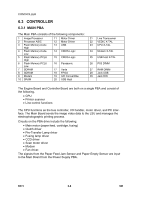
CONTROLLER 6.3 CONTROLLER 6.3.1 MAIN PBA The Main PBA consists of the following components: 1 Image Processor 2 Processor ASIC 3 Flash Memory-Code High 4 Flash Memory-Code Low 5 Flash Memory-PCL6 High 6 Flash Memory-PCL6 Low 7 SDRAM 8 SDRAM 9 Modem 10 SRAM 11 Motor Driver 12 Motor Driver 13 USB 14 CMOS-Logic 15 CMOS-Logic 16 Panasonic 17 Varta 18 FPGA 19 A/D Convertible 20 USB Host 21 Line Transceiver 22 VEDIC X-TAL 23 CPU X-TAL 24 Modem X-TAL 25 USB host X-TAL 26 PS3 DIMM 27 RAM DIMM 28 Jack USB 29 Jack DIN The Engine Board and Controller Board are both on a single PBA and consist of the following. • CPU • Printer scanner • Line control functions The CPU functions as the bus controller, I/O handler, motor driver, and PC interface. The Main Board sends the image video data to the LSU and manages the electrophotographic printing process. Circuits on the PBA drive include the following: • Main motor (paper feed, cartridge, fusing) • Clutch driver • Pre-Transfer Lamp driver • Fusing lamp driver • CCD driver • Scan motor driver • Modem • Fan driver. The signals from the Paper Feed Jam Sensor and Paper Empty Sensor are input to the Main Board from the Power Supply PBA. B273 6-8 SM
-
 1
1 -
2
-
3
-
4
-
5
-
6
-
7
-
8
-
9
-
10
-
11
-
12
-
13
-
14
-
15
-
16
-
17
-
18
-
19
-
20
-
21
-
22
-
23
-
24
-
25
-
26
-
27
-
28
-
29
-
30
-
31
-
32
-
33
-
34
-
35
-
36
-
37
-
38
-
39
-
40
-
41
-
42
-
43
-
44
-
45
-
46
-
47
-
48
-
49
-
50
-
51
-
52
-
53
-
54
-
55
-
56
-
57
-
58
-
59
-
60
-
61
-
62
-
63
-
64
-
65
-
66
-
67
-
68
-
69
-
70
-
71
-
72
-
73
-
74
-
75
-
76
-
77
-
78
-
79
-
80
-
81
-
82
-
83
-
84
-
85
-
86
-
87
-
88
-
89
-
90
-
91
-
92
-
93
-
94
-
95
-
96
-
97
-
98
-
99
-
100
-
101
-
102
-
103
-
104
-
105
-
106
-
107
-
108
-
109
-
110
-
111
-
112
-
113
-
114
-
115
-
116
-
117
-
118
-
119
-
120
-
121
-
122
-
123
-
124
-
125
-
126
-
127
-
128
-
129
-
130
-
131
-
132
-
133
-
134
-
135
-
136
-
137
-
138
-
139
-
140
-
141
-
142
-
143
-
144
-
145
-
146
-
147
-
148
-
149
-
150
-
151
-
152
-
153
-
154
-
155
-
156
-
 157
157 -
 158
158 -
 159
159 -
 160
160 -
 161
161 -
 162
162 -
 163
163 -
 164
164 -
 165
165 -
 166
166 -
 167
167 -
168
-
169
-
170
-
171
-
172
-
173
-
174
-
175
-
176
-
177
-
178
-
179
-
180
-
181
-
182
-
183
-
184
-
185
-
186
-
187
-
188
 |
 |
