Ricoh AC205 Service Manual - Page 164
SENSOR INPUT CIRCUIT, Paper Empty Sensor, By-pass Tray Sensor, Cover Open Sensor
 |
View all Ricoh AC205 manuals
Add to My Manuals
Save this manual to your list of manuals |
Page 164 highlights
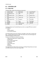
CONTROLLER 6.3.7 SENSOR INPUT CIRCUIT Paper Empty Sensor The Paper Empty Sensor (photointerrupter) is monitored by the CPU signal "nP_EMPTY". The machine shows a message on the LCD when the cassette is empty. By-pass Tray Sensor Paper in the By-pass Tray is detected by operation of the By-pass Sensor (photointerrupter). The CPU monitors signal "MP_EMPTY" to recognize paper in the by-pass tray. Paper is fed from the by-pass tray if there is paper present in the by-pass tray. Paper Feed Sensor When paper passes the actuator on the Feed Sensor, it is detected by the photointerrupter signal "nP_FEED". The signal is monitored by the CPU, and starts the process of creating the image after a specific time delay. Jam0 shows on the operation panel if the Feed Sensor is not detected within 1 sec. after paper is fed. The toner cartridge also operates the Paper Feed Sensor when it is inserted into the machine. A message shows on the operation panel if no cartridge is detected. Paper Exit Sensor An Exit Sensor on the Engine Board and an actuator on the frame detect when the paper exits cleanly from the machine. The sensor checks the signal "P_EXIT" and detects the on/off time of the Exit Sensor. Jam2 shows on the operation panel if a jam status is detected. Cover Open Sensor The Cover Open Sensor actuator is located on the front cover, (the sensor is located in the mainframe). Power (+24V) is cut to the following when the front cover is opened: • DC fan • Solenoid • Main motor • Polygon motor part of LSU The CPU monitors signal COVER_OPEN to recognize when the cover is opened. DC Fan/Solenoid Driving These are driven by a transistor and controlled by the signal "FAN SMPS, CON223 bit" of the CPU. The fan is activated by turning the transfer roller when the signal is high. The fan is deactivated when sleep mode is selected. There are two solenoids and both are driven by the paper pick-up and MP signals. The drive time is 300ms. A diode protects the driving TR from the back-EMF pulse, which is generated when the solenoid is de-energized. Motor Driving The motor driving circuit is activated when the driver IC is enabled. The resistance value of sensing and the voltage value of the V reference can be changed via the motor driving voltage value. B273 6-10 SM
-
 1
1 -
2
-
3
-
4
-
5
-
6
-
7
-
8
-
9
-
10
-
11
-
12
-
13
-
14
-
15
-
16
-
17
-
18
-
19
-
20
-
21
-
22
-
23
-
24
-
25
-
26
-
27
-
28
-
29
-
30
-
31
-
32
-
33
-
34
-
35
-
36
-
37
-
38
-
39
-
40
-
41
-
42
-
43
-
44
-
45
-
46
-
47
-
48
-
49
-
50
-
51
-
52
-
53
-
54
-
55
-
56
-
57
-
58
-
59
-
60
-
61
-
62
-
63
-
64
-
65
-
66
-
67
-
68
-
69
-
70
-
71
-
72
-
73
-
74
-
75
-
76
-
77
-
78
-
79
-
80
-
81
-
82
-
83
-
84
-
85
-
86
-
87
-
88
-
89
-
90
-
91
-
92
-
93
-
94
-
95
-
96
-
97
-
98
-
99
-
100
-
101
-
102
-
103
-
104
-
105
-
106
-
107
-
108
-
109
-
110
-
111
-
112
-
113
-
114
-
115
-
116
-
117
-
118
-
119
-
120
-
121
-
122
-
123
-
124
-
125
-
126
-
127
-
128
-
129
-
130
-
131
-
132
-
133
-
134
-
135
-
136
-
137
-
138
-
139
-
140
-
141
-
142
-
143
-
144
-
145
-
146
-
147
-
148
-
149
-
150
-
151
-
152
-
153
-
154
-
155
-
156
-
157
-
158
-
 159
159 -
 160
160 -
 161
161 -
 162
162 -
 163
163 -
 164
164 -
 165
165 -
 166
166 -
 167
167 -
 168
168 -
 169
169 -
170
-
171
-
172
-
173
-
174
-
175
-
176
-
177
-
178
-
179
-
180
-
181
-
182
-
183
-
184
-
185
-
186
-
187
-
188
 |
 |
