Ricoh AC205 Service Manual - Page 74
DRIVE ASSEMBLY, plate. Tighten the screws in the order shown on the plate, when
 |
View all Ricoh AC205 manuals
Add to My Manuals
Save this manual to your list of manuals |
Page 74 highlights
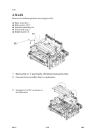
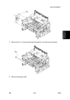
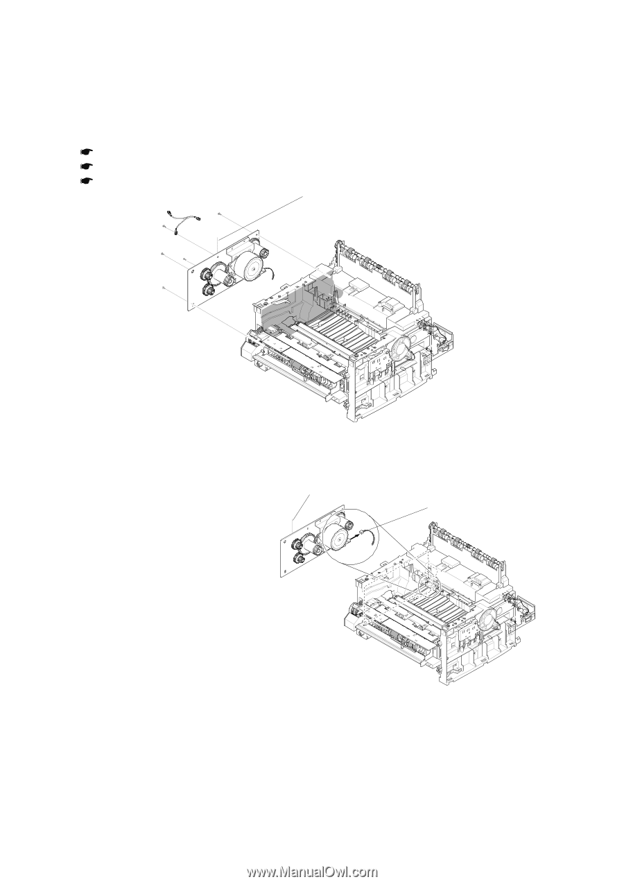
DRIVE ASSEMBLY 3.14 DRIVE ASSEMBLY Remove the following before removing the drive assembly: Rear cover 3.2.1 Side covers 3.2.2 Controller shield assembly 3.7 [A] 1. Remove the 5 x securing the drive assembly. [B] 2. Remove the drive assembly [B]. 3. Unplug the 1 x [C] from the motor PBA. B273R955.WMF [C] B273R957.WMF NOTE: The six screws have numbers stamped on the drive assembly base plate. Tighten the screws in the order shown on the plate, when reassembling the drive assembly. It is necessary to consider only screws one to five at the time of drive assembly replacement. Screw number six is tightened when the controller shield assembly is replaced. B273 3-38 SM
-
 1
1 -
2
-
3
-
4
-
5
-
6
-
7
-
8
-
9
-
10
-
11
-
12
-
13
-
14
-
15
-
16
-
17
-
18
-
19
-
20
-
21
-
22
-
23
-
24
-
25
-
26
-
27
-
28
-
29
-
30
-
31
-
32
-
33
-
34
-
35
-
36
-
37
-
38
-
39
-
40
-
41
-
42
-
43
-
44
-
45
-
46
-
47
-
48
-
49
-
50
-
51
-
52
-
53
-
54
-
55
-
56
-
57
-
58
-
59
-
60
-
61
-
62
-
63
-
64
-
65
-
66
-
67
-
68
-
 69
69 -
 70
70 -
 71
71 -
 72
72 -
 73
73 -
 74
74 -
 75
75 -
 76
76 -
 77
77 -
 78
78 -
 79
79 -
80
-
81
-
82
-
83
-
84
-
85
-
86
-
87
-
88
-
89
-
90
-
91
-
92
-
93
-
94
-
95
-
96
-
97
-
98
-
99
-
100
-
101
-
102
-
103
-
104
-
105
-
106
-
107
-
108
-
109
-
110
-
111
-
112
-
113
-
114
-
115
-
116
-
117
-
118
-
119
-
120
-
121
-
122
-
123
-
124
-
125
-
126
-
127
-
128
-
129
-
130
-
131
-
132
-
133
-
134
-
135
-
136
-
137
-
138
-
139
-
140
-
141
-
142
-
143
-
144
-
145
-
146
-
147
-
148
-
149
-
150
-
151
-
152
-
153
-
154
-
155
-
156
-
157
-
158
-
159
-
160
-
161
-
162
-
163
-
164
-
165
-
166
-
167
-
168
-
169
-
170
-
171
-
172
-
173
-
174
-
175
-
176
-
177
-
178
-
179
-
180
-
181
-
182
-
183
-
184
-
185
-
186
-
187
-
188
 |
 |
DRIVE ASSEMBLY
B273
3-38
SM
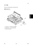
3.14 DRIVE ASSEMBLY
Remove the following before removing the drive assembly:
Rear cover 3.2.1
Side covers 3.2.2
Controller shield assembly 3.7
1. Remove the 5 x
securing the drive assembly.
2. Remove the drive assembly
[B].
3. Unplug the 1 x
[C] from
the motor PBA.
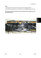
NOTE:
The six screws have numbers stamped on the drive assembly base
plate. Tighten the screws in the order shown on the plate, when
reassembling the drive assembly. It is necessary to consider only
screws one to five at the time of drive assembly replacement. Screw
number six is tightened when the controller shield assembly is
replaced.
B273R955.WMF
B273R957.WMF
[A]
[B]
[C]