Ricoh AC205 Service Manual - Page 157
System Layout, Paper Feed, Transfer Assembly, Drive Assembly
 |
View all Ricoh AC205 manuals
Add to My Manuals
Save this manual to your list of manuals |
Page 157 highlights
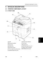
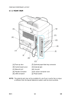
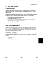
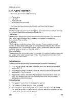
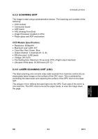
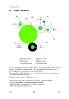
SYSTEM LAYOUT 6.2 SYSTEM LAYOUT 6.2.1 PAPER FEED The paper tray unit and the manual by-pass unit automatically feed paper to the machine. A friction pad separates the paper and ensures that paper is fed one sheet at a time. A sensor checks when the paper tray is empty. At this time a message appears on the operation panel. (There is no Paper Near End Sensor in this machine.) • Feeding Method: Universal Cassette Type • Feeding Standard: Center Loading • Feeding Capacity: Cassette-250 sheets (75g/m2, 20lb paper standard) • Manual: 1 sheet (paper, OHP, envelop, etc.) • Paper detecting sensor: Photo sensor • Paper size sensor: None 6.2.2 TRANSFER ASSEMBLY The transfer assembly consists of the PTL (Pre-Transfer Lamp) and the transfer roller. The PTL sends light to the OPC drum. This light lowers the charge on the drum's surface, and improves transfer efficiency. The transfer roller moves toner from the OPC drum surface to the paper. 6.2.3 DRIVE ASSEMBLY The drive assembly is a gear-driven power unit. The motor supplies power to the following: • Paper feed unit • Fusing unit • Toner cartridge Detailed Descriptions SM 6-3 B273
-
 1
1 -
2
-
3
-
4
-
5
-
6
-
7
-
8
-
9
-
10
-
11
-
12
-
13
-
14
-
15
-
16
-
17
-
18
-
19
-
20
-
21
-
22
-
23
-
24
-
25
-
26
-
27
-
28
-
29
-
30
-
31
-
32
-
33
-
34
-
35
-
36
-
37
-
38
-
39
-
40
-
41
-
42
-
43
-
44
-
45
-
46
-
47
-
48
-
49
-
50
-
51
-
52
-
53
-
54
-
55
-
56
-
57
-
58
-
59
-
60
-
61
-
62
-
63
-
64
-
65
-
66
-
67
-
68
-
69
-
70
-
71
-
72
-
73
-
74
-
75
-
76
-
77
-
78
-
79
-
80
-
81
-
82
-
83
-
84
-
85
-
86
-
87
-
88
-
89
-
90
-
91
-
92
-
93
-
94
-
95
-
96
-
97
-
98
-
99
-
100
-
101
-
102
-
103
-
104
-
105
-
106
-
107
-
108
-
109
-
110
-
111
-
112
-
113
-
114
-
115
-
116
-
117
-
118
-
119
-
120
-
121
-
122
-
123
-
124
-
125
-
126
-
127
-
128
-
129
-
130
-
131
-
132
-
133
-
134
-
135
-
136
-
137
-
138
-
139
-
140
-
141
-
142
-
143
-
144
-
145
-
146
-
147
-
148
-
149
-
150
-
151
-
 152
152 -
 153
153 -
 154
154 -
 155
155 -
 156
156 -
 157
157 -
 158
158 -
 159
159 -
 160
160 -
 161
161 -
 162
162 -
163
-
164
-
165
-
166
-
167
-
168
-
169
-
170
-
171
-
172
-
173
-
174
-
175
-
176
-
177
-
178
-
179
-
180
-
181
-
182
-
183
-
184
-
185
-
186
-
187
-
188
 |
 |