Yamaha CL3 Owner's Manual
Yamaha CL3 Manual
 |
View all Yamaha CL3 manuals
Add to My Manuals
Save this manual to your list of manuals |
Yamaha CL3 manual content summary:
- Yamaha CL3 | Owner's Manual - Page 1
Owner's Manual Keep This Manual For Future Reference. EN - Yamaha CL3 | Owner's Manual - Page 2
About utility software 7 About firmware updates 7 About the Owner's Manual 7 Conventions in this manual 7 An overview of the CL series 8 Features 8 About the models 9 Controls and functions 10 Top panel 10 Front Panel 16 Rear Panel 16 Touch screen 18 Basic touch screen operations 18 The - Yamaha CL3 | Owner's Manual - Page 3
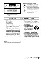
the user to the presence of important operating and maintenance (servicing) instructions in the literature accompanying the product. IMPORTANT SAFETY INSTRUCTIONS 1 Read these instructions. 2 Keep these instructions. 3 Heed all warnings. 4 Follow all instructions. 5 Do not use this apparatus near - Yamaha CL3 | Owner's Manual - Page 4
Yamaha Corporation of America Address : 6600 Orangethorpe Ave., Buena Park, Calif. 90620 Telephone : 714-522-9011 Type of Equipment : Digital Mixing Console Model Name : CL5/CL3/CL1 This device complies with Part 15 of the FCC Rules. Operation undesired operation. See user manual instructions if - Yamaha CL3 | Owner's Manual - Page 5
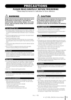
manual in a safe place for future reference. WARNING Always follow the basic precautions listed problems occur, immediately turn off the power switch and disconnect the electric plug from the outlet. Then have the device inspected by Yamaha service accessible. If some trouble or malfunction occurs, - Yamaha CL3 | Owner's Manual - Page 6
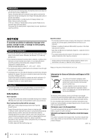
, digital versatile discs, amiconductor chips, hard drives, memory cards and the like). An independent license for such use is required. For ditails, please visit http://mp3licensing.com/ About this manual * The illustrations and LCD screens as shown in this manual are for instructional purposes - Yamaha CL3 | Owner's Manual - Page 7
you for choosing a Yamaha CL series CL5/CL3/CL1 Digital Mixing Console. To take full advantage of the superior features and performance offered by your CL-series console, and to enjoy years of trouble-free use, please read this owner's manual carefully before operating your console. After you have - Yamaha CL3 | Owner's Manual - Page 8
to the console. CL StageMix, an application for iPads, offers remote control of a networked CL series console from anywhere within wireless range via an intuitive graphical interface. The software has been specifically designed to allow engineers to adjust EQ while monitoring mixes from the - Yamaha CL3 | Owner's Manual - Page 9
digital domain You can cascade a second CL series unit or a digital mixer, such as the Yamaha M7CL, PM5D or LS9, connected via a digital I/O card installed in a slot. You can cascade any of the MIX the ideal operating environment for yourself. Help file downloadable to the unit You can download from - Yamaha CL3 | Owner's Manual - Page 10
and functions Controls and functions Top panel The top panel of the CL series is divided into the following sections. 2 3 6 j 9 5 1 4 7 connector ➔ page 15 0 Meter section (for CL5 only) ➔ page 15 NOTE This illustration shows the top panel of the CL5. The CL3 and CL1 do not feature a - Yamaha CL3 | Owner's Manual - Page 11
If you control an you control a channel in the the selected object of control will alternate between the the currently-selected MIX/MATRIX bus. the currently-selected MIX/MATRIX bus. control when the ASSIGN function is selected. 0 Bank Select keys These keys switch the channel faders controlled - Yamaha CL3 | Owner's Manual - Page 12
). 1 [MIX1-16] key/[MIX17-24/MATRIX]key Select a MIX or MATRIX bus that is controlled by the knobs located below the keys. 2 [1]-[16] knobs input channel. On the other hand, it adjusts the digital gain if GAIN KNOB FUNCTION is set to DIGITAL GAIN in the PREFERENCE tab of the USER SETUP screen Manual - Yamaha CL3 | Owner's Manual - Page 13
to select menus or set parameters. Please note that you cannot operate the unit by touching multiple points simultaneously. NOTE If the touch right of the key) to the Centralogic section. 2 Multifunction knob Controls the knob currently selected on the touch screen. The knob function can Manual 13 - Yamaha CL3 | Owner's Manual - Page 14
operations for scene memory and monitoring. 34 5 USER DEFINED KNOBS section USER DEFINED knobs [A]-[D] Control the parameters that have been assigned by the user (input channel digital Stores the current mix parameter settings in future updated versions. This function is not featured in firmware - Yamaha CL3 | Owner's Manual - Page 15
assigned, the selected object of control will alternate between the L and to record or play audio files, and to save operation of all USB flash drives.) The FAT16 and FAT32 formats are supported CL unit or on your media device. Meter section (for CL5 only) Indicates the level of MIX Manual 15 - Yamaha CL3 | Owner's Manual - Page 16
phantom power to this jack. This jack sends instructions from the mixer operator to the desired output channel. 4 TALKBACK LEVEL updated versions. This function is not featured in firmware version 1.0. A BDC 5 DIGITAL OUT connector An AES/EBU (XLR-3-32 male) jack that outputs the digital audio - Yamaha CL3 | Owner's Manual - Page 17
Yamaha dealer. 8 Dante connectors Used to connect to other Dante control mix parameters or to edit scene memories and libraries from the dedicated "CL Editor" application program or "StageMix" iPad is connected, the CL series will operate correctly whether its power cable to the CL unit, then insert - Yamaha CL3 | Owner's Manual - Page 18
key once, but in certain cases you can access special functions by rapidly pressing a key twice in succession. Knob operations Typically, knobs are rotated left or right to change the value of the corresponding parameter. By pressing a knob, you can recall a specific screen. For certain parameters - Yamaha CL3 | Owner's Manual - Page 19
for a specific parameter in a screen, a window showing detailed parameters or lists will appear. operation. Press the arrow / below the list to scroll the list up or down. NOTE • You can also scroll the list recall libraries or to perform copy and paste operations. Press the "X" symbol to close the - Yamaha CL3 | Owner's Manual - Page 20
CL In this case, the type send-destination MIX/MATRIX specific settings. A RECORDER When you press this button, the recorder screen will appear in the main area, allowing you to operate and make settings of the recorder function for recording and playing back audio the SCENE LIST screen will Manual - Yamaha CL3 | Owner's Manual - Page 21
operations will involve mainly the following two types of screens. ■ SELECTED CHANNEL VIEW screen This screen shows all the mix parameters for the currently-selected channel. To access this screen, press one of the knobs of the SELECTED CHANNEL section. Entering names Entering names On the CL - Yamaha CL3 | Owner's Manual - Page 22
move the input position. If you select a region of characters entered in the box and then enter a new character, the newly-entered character will overwrite the selected region. Using the tool buttons In some popup windows, windows, some of the various tool buttons also appear. 22 Owner's Manual - Yamaha CL3 | Owner's Manual - Page 23
EQ library • Dynamics library • GEQ library • Effect library • Dante input patch library • Premium Rack library The method of operation is essentially the same for each library. NOTE Premium Rack library GEQ/effect/Premium Rack is already mounted. 1 2 1 RACK button 2 Racks Owner's Manual 23 - Yamaha CL3 | Owner's Manual - Page 24
TYPE (Only for output channel library) This field displays the type of channel selected via the [SEL] key. 2 List This list shows the data saved in the library. A highlighted line indicates that it is selected for operations. Read-only data is indicated by an R symbol. NOTE The right side of the - Yamaha CL3 | Owner's Manual - Page 25
list different from the one selected in the list in the output channel library, "CONFLICT not be able to perform the Store operation. 3. At the top of the popup the position selected in the list. 4. Turn one of to confirm the Store operation. 7. To execute the Store operation, press the OK button - Yamaha CL3 | Owner's Manual - Page 26
button erases the settings that are selected in the list. 3. Turn one of the multifunction knobs to select instead of the OK button. NOTE In the case of EQ/dynamics, you can use the channel channels and initialize them in a single operation. Copying/pasting settings This section explains how Manual - Yamaha CL3 | Owner's Manual - Page 27
select multiple channels as the paste-destination. In this case, the same content will be pasted to all selected the buffer memory. Unlike the Paste operation, the Compare operation always lets you return to the buffer memory can also be used for the Paste operation. • Of the two types of GEQ, using - Yamaha CL3 | Owner's Manual - Page 28
will operate the CL series for mixing using a combination of these operations. Controlling selected channels (SELECTED CHANNEL section) The SELECTED CHANNEL section located to the left of the display corresponds to the mixer module on a conventional analog mixer, and allows you to manually adjust - Yamaha CL3 | Owner's Manual - Page 29
controls affect INPUT channels 1-8 in the OVERVIEW screen. These controls affect DCA groups 1-8. 3. To release the channels or DCA groups that were retained for the Centralogic section, press the Bank Select key you operated The CUSTOM FADER BANK / MASTER FADER screen will appear. Owner's Manual 29 - Yamaha CL3 | Owner's Manual - Page 30
operation of the CL series 4. Select a target custom fader bank. Channel strips are categorized into four blocks; from your left, block A, block B (Centralogic section), block C (only for CL5 specific MIX bus. 1. In the function access area in the display, press the SENDS ON FADER button. 1 The CL - Yamaha CL3 | Owner's Manual - Page 31
remotely control I/O racks or amplifiers from a mixing console; or make multi-track recordings to a DAW, such as Nuendo, installed on a computer in the network. Visit the Audinate website for more details on Dante. http://www.audinate.com/ Additional information on Dante is also posted on the Yamaha - Yamaha CL3 | Owner's Manual - Page 32
EF012 Connections About Dante Controller Dante Controller is a software application that allows configuration and audio routing of Dante networks. Use this application if you plan to connect or set up Dante-enabled devices (such as Dante-MY16-AUD) that do not feature CL native support, or if you - Yamaha CL3 | Owner's Manual - Page 33
DANTE SETUP screen. 2. Turn off to the power to the CL unit. 3. Use the Dante connectors on the CL series and I/O racks to connect them as follows: Network switch PRIMARY CL5 SECONDARY PRIMARY 789A Audio EF012 EF012 5. Turn on the power to the CL series and the I/O rack units. Owner's Manual 33 - Yamaha CL3 | Owner's Manual - Page 34
input/output jacks to the CL or connect speaker processor units. Refer to the Yamaha professional audio website for the most recent information on available I/O cards. http://www.yamahaproaudio.com/ 34 Owner's Manual Slot cover 3. Align the edges of the card with the guide rails inside the slot - Yamaha CL3 | Owner's Manual - Page 35
Setup This section explains the setup required when starting up the CL series for the first time. This section will also discuss basic operations for sending an input channel signal out from the STEREO bus so in a range of 0-23) 12Hours (hours shown from 0am-11am, and 0pm- 11pm) Owner's Manual 35 - Yamaha CL3 | Owner's Manual - Page 36
DANTE 44.1k button. • When using clock data from a digital audio signal as the clock source Press a valid two-channel button for the corresponding slot. • When using word clock data from the WORD CLOCK IN jack as the clock source Press the WORD CLOCK IN button. If the CL unit is operating 's Manual - Yamaha CL3 | Owner's Manual - Page 37
are two ways to control channel parameters on the CL unit: using the Centralogic section to operate the corresponding knobs to light at the highest audio input level. The input controlled by the Centralogic section, and adjust the gain for the other input channels in the same way. Owner's Manual 37 - Yamaha CL3 | Owner's Manual - Page 38
with the mic, instrument, and main speakers are appropriate. In this case as well, you can either use the SELECTED CHANNEL section to make settings Press the [SEL] key of the input channel that you want to control. 2. Press one of the knobs in the SELECTED CHANNEL section. The 38 Owner's Manual - Yamaha CL3 | Owner's Manual - Page 39
eight channels at a time. 1. Press a Bank Select key so that the input channels you want to control are assigned to the Centralogic section. The selected eight channels are shown in the OVERVIEW screen. Sending an input the speaker system that is patched to the STEREO channel. Owner's Manual 39 - Yamaha CL3 | Owner's Manual - Page 40
the functions and their parameters, refer to the Reference Manual. Connecting the devices 1. Make sure that power to all devices to be connected is turned off. Then, use an Ethernet cable to connect the Dante PRIMARY connector on the CL to the Dante PRIMARY connector on the I/O rack. 2. Set the ID - Yamaha CL3 | Owner's Manual - Page 41
Patching the mixer output to the I/O rack 1. Press the RACK button power on or off 1. Press the [SEL] key for the channel that you want to control in the Channel Strip section or Centralogic section. 2. Press the GAIN knob in the SELECTED [CUE] key off (the key LED turns off). Owner's Manual 41 - Yamaha CL3 | Owner's Manual - Page 42
Guide Applying EQ/dynamics Applying EQ 1. Press the [SEL] key of the channel that you want to control SEL] key of the output channel that you want to control. 3. Press any one of the knobs in the the [SEL] key of the channel that you want to control. 2. Press the ON button of the DYNAMICS 1 field in - Yamaha CL3 | Owner's Manual - Page 43
FADER ASSIGN to select the GEQ you will control using the Centralogic section's faders. 6. Select an effect you want to use from the EFFECT TYPE popup window. 9. Perform the same operations for other GEQs as desired. NOTE The the channel to which you want to apply the effect. Owner's Manual 43 - Yamaha CL3 | Owner's Manual - Page 44
Quick Guide 8. Press the SENDS ON FADER button in the display want to use. 11. Use the faders of the Channel Strip section to control effect sends. 12. Press the X symbol for the MIX 1-16/MIX17-24/MATRIX button to exit SENDS ON FADER mode. 13. In column. 7. Press the CLOSE button. 44 Owner's Manual - Yamaha CL3 | Owner's Manual - Page 45
for INSERT or DIRECT OUT. 5. Press the ON button to enable it. 6. Modify the INSERT or DIRECT OUT point by pressing it, if necessary. Owner's Manual 45 - Yamaha CL3 | Owner's Manual - Page 46
, and press the [SEL] key for the other channel. NOTE You can also set or release a channel link in the display. Setting a DCA or MUTE group 1. Press the [SEL] key of the channel that you want to control. 2. Press the DCA tab or MUTE tab in the SELECTED CHANNEL screen. 3. Press the - Yamaha CL3 | Owner's Manual - Page 47
, select other channels that you want to assign. 6. While observing the TALKBACK IN meter, use the front panel VOLUME knob to adjust the level. Owner's Manual 47 - Yamaha CL3 | Owner's Manual - Page 48
Quick Guide Routing the oscillator to an output channel 1. Press the MONITOR button in the display screen. 2. Press the setting button in the OSCILLATOR tab to select the output destination. 5. Return to the previous screen, then press the OUTPUT button in the OSCILLATOR area. 48 Owner's Manual - Yamaha CL3 | Owner's Manual - Page 49
to the CL unit. 2. Press the RECORDER button in the display screen. 3. In the PLAYBACK OUT field, select a channel from which you want to play audio files. 4. In the RECORDER INPUT field, select a recording source channel and set the recording level. 4. Select an audio file to play from the list - Yamaha CL3 | Owner's Manual - Page 50
file list, or rotate a multifunction knob on the panel. 4. Press the LOAD button. 3. Press the SAVE/LOAD button. 4. If necessary, press the directory icon and change the directory. To move to the next higher level, press the arrow button in the PATH field. Formatting a USB flash drive on the CL - Yamaha CL3 | Owner's Manual - Page 51
CL's internal memory, or if you forget the password and cannot operate operation the CL CL will start up in normal operating mode. NOTE Alternatively, you can continue the operation CL, the power will turn on regardless of whether you first turn on the power switch of the CL operation the mix parameters - Yamaha CL3 | Owner's Manual - Page 52
EXIT button. The CL unit will start up in normal operating mode. NOTE Alternatively, you can continue the operation by selecting a specified faders will move to the target positions in the following sequence. Manually move the faders to the correct positions. 1 -∞ (all the way down) 2 -20dB - Yamaha CL3 | Owner's Manual - Page 53
/2 be set to ducking or to an extreme parameter value? Operating a fader does not control the level as you expect. ❍ Could the function access area indicate MIX/MTRX ON FADER? And could SENDS ON FADER mode be engaged? Only the sound of a specific channel is heard from the MONITOR OUT or PHONES jack - Yamaha CL3 | Owner's Manual - Page 54
parameters will not be updated? ❍ Could user level specific frequency to be decreased. Cannot control an I/O rack. ❍ Are the rotary switch and DIP switches on the I/O racks set correctly? ❍ Does the channel being controlled match the channel on the I/O rack? Cannot control the CL unit from CL Editor - Yamaha CL3 | Owner's Manual - Page 55
to the Yamaha pro audio website for information on supported cards. http Specifications and descriptions in this owner's manual are for information purposes only. Yamaha Corp. reserves the right to change or modify products or specifications at any time without prior notice. Since specifications - Yamaha CL3 | Owner's Manual - Page 56
the body to preset the maximum output level. *6. The position of the level control is 10dB lowered from Max. DIGITAL INPUT & OUTPUT CHARACTERISTICS Terminal Primary/Secondary Format Dante Data length Level 24bit or 32bit 1000Base-T Audio 64ch Input/64ch Output @48kHz Connector EtherCON Cat5e - Yamaha CL3 | Owner's Manual - Page 57
GPI2 7 GPI3 15 GPI4 8 GPI5 5 1 9 6 METER (CL3/CL1 only) Pin Signal Name Pin 1 RESET 6 2 SDA 7 3 DGND 8 4 SCL 9 5 +3.3D Signal Name +3.3LD +3.3LD LDGND LDGND Owner's Manual 57 - Yamaha CL3 | Owner's Manual - Page 58
Dimensions Dimensions 15 CL5 299 201 667 CL3 1053 15 130 299 201 667 CL1 839 15 130 299 201 667 58 648 Owner's Manual 130 Unit: mm - Yamaha CL3 | Owner's Manual - Page 59
settings 29 D Daisy chain network 32 Dante 8, 31 Dante Controller 32 DCA group 46 Dialog 19 DIRECT Lamps 35 Linking 46 List windows 19 Llibraries 23 Index M Main area 21 MIX/MATRIX bus 30 Master section 15 Meter section (for CL5 only 15 SCENE MEMORY/MONITOR section Manual 59 - Yamaha CL3 | Owner's Manual - Page 60
- Yamaha CL3 | Owner's Manual - Page 61
GAIN To MONITOR SELECT RECORDER CUE DANTE IN 1-64 OMNI IN 1-8 To 72 {64, 48} OSCILLATOR Digital GAIN INSERT 4BAND HPF ATT EQ FADER)PFL / (POST ON)AFL / POST PAN L To MIX VARI STEREO PRE EQ / PRE FADER / POST ON To MATRIX OUT A(L)/B(R) Refer to CL5/CL3/CL1 Mixer Block Diagram 2/2 PREMIUM - Yamaha CL3 | Owner's Manual - Page 62
OUT L,R STEREO OUT MONO(C) MIX OUT1-24 MATRIX OUT1-8 DEFINE MIX (MAX:8ch) MONITOR SELECT MIX CASCADE OUT 1-24 STEREO CASCADE OUT L,R, CH INSERT OUT 1-72{64,48} MIX INSERT OUT 1-24 STEREO INSERT OUT L,R, OUTPUT PATCH GAIN DELAY METER DANTE OUT (MAX:1000ms) 64 DANTE OUTPUT [DANTE OUT] (1-64) OUTPUT - Yamaha CL3 | Owner's Manual - Page 63
-160 31 -190 32 -170 -200 33 34 -180 -210 35 36 -190 IN OUT IN CASCADE IN CASCADE OUT OUT Digital Analog OUTPUT PATCH DELAY 㪫㪩㪠㪤 DA Analog dBu Digital Clipping Level Max. DSP Noise Floor Max. Output [+24dBu] Nominal Output [+4dBu] PHONES Max Output (150mW@8㱅) Nominal Output (75mW - Yamaha CL3 | Owner's Manual - Page 64
Yamaha representative or the authorized distributor listed below. Pour plus de détails sur les produits, veuillez-vous adresser à Yamaha ou au distributeur le plus proche de vous figurant dans la liste ARGENTINA Yamaha Music Yamaha Yamaha Yamaha Yamaha Music Yamaha Corporation, Asia-Pacific Sales - Yamaha CL3 | Owner's Manual - Page 65
Yamaha Pro Audio Global Web Site http://www.yamahaproaudio.com/ Yamaha Manual Library http://www.yamaha.co.jp/manual/ C.S.G., Pro Audio Division © 2012 Yamaha Corporation 204IPTO-A0 Printed in Japan ZC58320
-
 1
1 -
 2
2 -
 3
3 -
 4
4 -
 5
5 -
 6
6 -
 7
7 -
8
-
9
-
10
-
11
-
12
-
13
-
14
-
15
-
16
-
17
-
18
-
19
-
20
-
21
-
22
-
23
-
24
-
25
-
26
-
27
-
28
-
29
-
30
-
31
-
32
-
33
-
34
-
35
-
36
-
37
-
38
-
39
-
40
-
41
-
42
-
43
-
44
-
45
-
46
-
47
-
48
-
49
-
50
-
51
-
52
-
53
-
54
-
55
-
56
-
57
-
58
-
59
-
60
-
61
-
62
-
63
-
64
-
65
 |
 |
EN
Owner’s Manual
Keep This Manual For Future Reference.