Yamaha CL3 Owner's Manual - Page 16
Front Panel, Rear Panel, WORD CLOCK IN/OUT connectors - firmware update
 |
View all Yamaha CL3 manuals
Add to My Manuals
Save this manual to your list of manuals |
Page 16 highlights
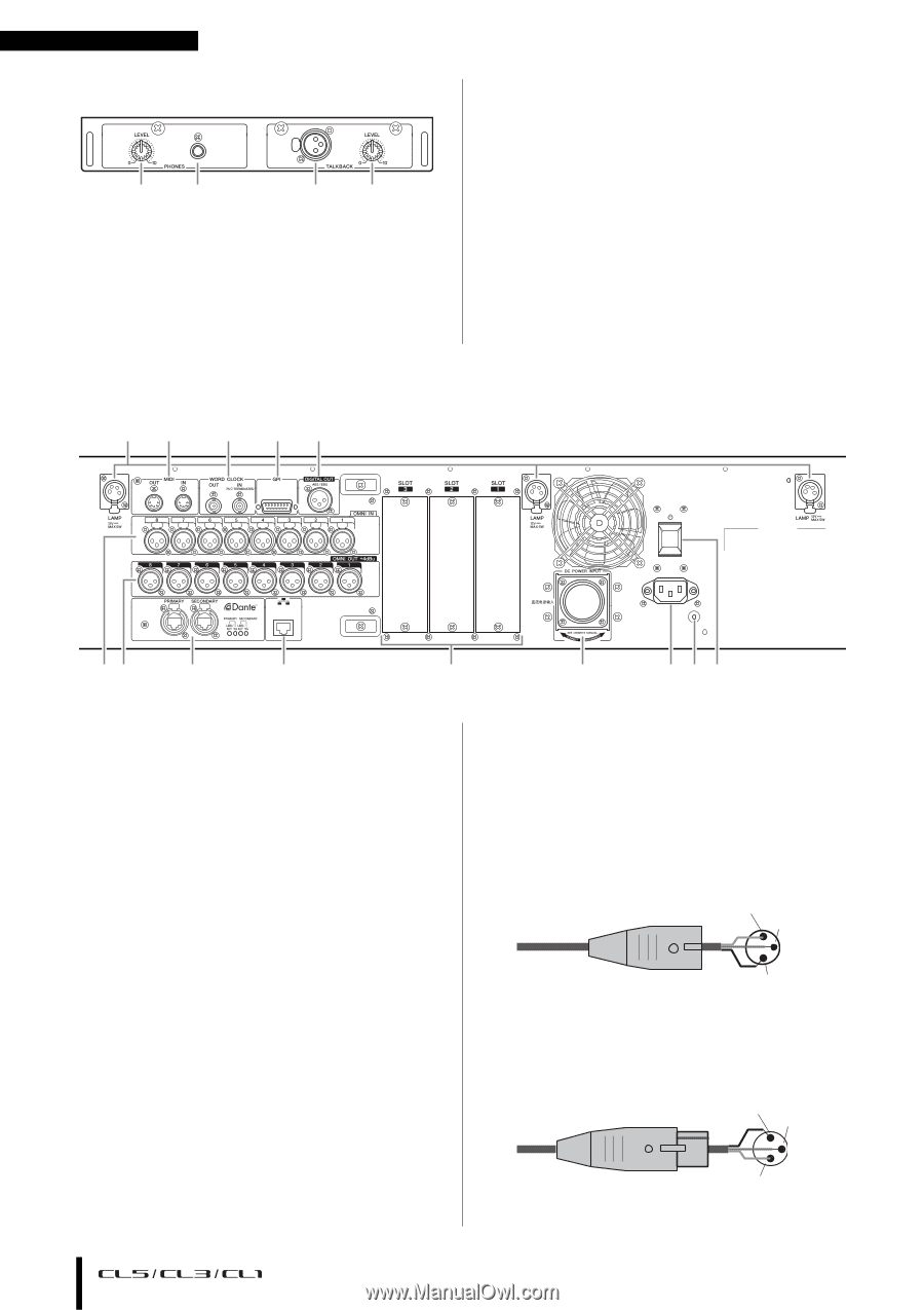
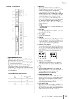
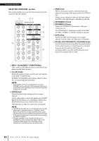
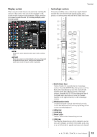
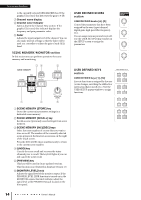
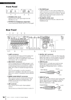
Controls and functions Front Panel 12 34 1 PHONES LEVEL knob Adjusts the level of the signal output from the PHONES Out jack. 2 PHONES Out (headphone output) jack Lets you monitor the MONITOR OUT or CUE signal. 3 TALKBACK jack A balanced XLR-3-31 jack to which a talkback mic can be connected. You can make settings in the screen to supply +48V phantom power to this jack. This jack sends instructions from the mixer operator to the desired output channel. 4 TALKBACK LEVEL knob Adjusts the input level of the mic connected to the TALKBACK jack. Rear Panel 12 3 45 67 8 9 0 1 LAMP connectors Four-pin female XLR output jacks that supply power to separately-sold gooseneck lamps (such as the Yamaha LA1L). (The CL3 includes these connectors at two locations. The CL1 includes one.) 2 MIDI IN/OUT connectors Used to transmit and receive MIDI messages to and from external MIDI devices. The MIDI IN connector receives messages from an external device, and the MIDI OUT connector transmits messages from the CL unit. These are used mainly to record CL parameter operations or scene/library selections on an external device, or to control CL parameters from an external device. 3 WORD CLOCK IN/OUT connectors BNC connectors used to transmit and receive word clock signals to and from an external device. The WORD CLOCK IN connector features internal 75-ohm termination. 4 GPI connector This connector will be used in future updated versions. This function is not featured in firmware version 1.0. A BDC 5 DIGITAL OUT connector An AES/EBU (XLR-3-32 male) jack that outputs the digital audio signal of a desired channel in AES/EBU format. This connector is used mainly to output the signal of the STEREO/MONO channels. 6 OMNI IN jacks Balanced XLR-3-31 female input jacks that input analog audio signals from line level devices or microphones. Nominal input level is −62 dBu to +10 dBu. Male XLR plug 1 (Ground) 3 (Cold) 2 (Hot) 7 OMNI OUT jacks XLR-3-32 male output jacks that output analog audio signals. These jacks are used mainly to output the signals of MIX channels or MATRIX channels. Nominal output level is +4 dBu. Female XLR plug 2 (Hot) 3 (Cold) 1 (Ground) 16 Owner's Manual
-
 1
1 -
2
-
3
-
4
-
5
-
6
-
7
-
8
-
9
-
10
-
 11
11 -
 12
12 -
 13
13 -
 14
14 -
 15
15 -
 16
16 -
 17
17 -
 18
18 -
 19
19 -
 20
20 -
 21
21 -
22
-
23
-
24
-
25
-
26
-
27
-
28
-
29
-
30
-
31
-
32
-
33
-
34
-
35
-
36
-
37
-
38
-
39
-
40
-
41
-
42
-
43
-
44
-
45
-
46
-
47
-
48
-
49
-
50
-
51
-
52
-
53
-
54
-
55
-
56
-
57
-
58
-
59
-
60
-
61
-
62
-
63
-
64
-
65
 |
 |