Yamaha CL3 Owner's Manual - Page 14
SCENE MEMORY/MONITOR USER DEFINED KNOBS, Channel name display - firmware
 |
View all Yamaha CL3 manuals
Add to My Manuals
Save this manual to your list of manuals |
Page 14 highlights
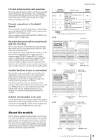
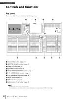
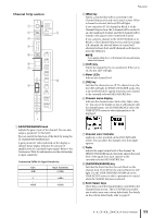
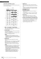
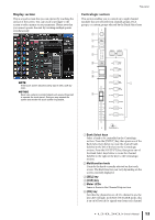
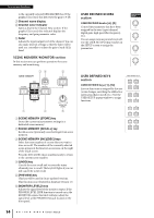
Controls and functions to the currently-selected MIX/MATRIX bus. If the graphic EQ is used, this key resets the gain to 0 dB. 7 Channel name display 8 Channel color indicator Same as that in the Channel Strip section. If the graphic EQ is used, this indicator displays the frequency and gain parameter value. 9 Fader Adjusts the input/output level of the channel. You can also make internal settings so that the fader will be used as a controller to adjust the gain of each GEQ band. SCENE MEMORY/MONITOR section In this section you can perform operations for scene memory and monitoring. 34 5 USER DEFINED KNOBS section USER DEFINED knobs [A]-[D] Control the parameters that have been assigned by the user (input channel digital gain, high-pass filter frequency, etc.). You can assign various parameters at will. Use the USER SETUP popup window in the SETUP screen to assign the parameters. USER DEFINED KEYS section USER DEFINED keys [1]-[16] Execute functions as assigned by the user (scene changes, switching the talkback or internal oscillator on/off, etc.). Use the USER SETUP popup window to assign functions. 1 2 6 1 SCENE MEMORY [STORE] key Stores the current mix parameter settings in a dedicated scene memory. 2 SCENE MEMORY [RECALL] key Recalls a scene (previously-saved settings) from scene memory. 3 SCENE MEMORY [INC]/[DEC] keys Select the scene number of a scene that you want to store or recall. The number of the currently-selected scene appears in the function access area on the right of the touch screen. Press the [INC]/[DEC] keys simultaneously to return to the current scene number. 4 [UNDO] key Cancels the scene recall and recovers the status obtained prior to recall. The key LED lights if you can still cancel the scene recall. 5 [PREVIEW] key This key will be used in future updated versions. This function is not featured in firmware version 1.0. 6 [MONITOR LEVEL] knob Adjusts the signal level of the monitor output. If the PHONES LEVEL LINK function is turned on in the MONITOR screen, this knob will also adjust the signal level at the PHONES Out jack located on the front panel. 14 Owner's Manual
-
 1
1 -
2
-
3
-
4
-
5
-
6
-
7
-
8
-
 9
9 -
 10
10 -
 11
11 -
 12
12 -
 13
13 -
 14
14 -
 15
15 -
 16
16 -
 17
17 -
 18
18 -
 19
19 -
20
-
21
-
22
-
23
-
24
-
25
-
26
-
27
-
28
-
29
-
30
-
31
-
32
-
33
-
34
-
35
-
36
-
37
-
38
-
39
-
40
-
41
-
42
-
43
-
44
-
45
-
46
-
47
-
48
-
49
-
50
-
51
-
52
-
53
-
54
-
55
-
56
-
57
-
58
-
59
-
60
-
61
-
62
-
63
-
64
-
65
 |
 |
