Yamaha CL3 Owner's Manual - Page 12
SELECTED CHANNEL MIX1-16] key/[MIX17-24/MATRIX]key, GAIN] knob, DYNAMICS 1] knob, HPF] knob
 |
View all Yamaha CL3 manuals
Add to My Manuals
Save this manual to your list of manuals |
Page 12 highlights
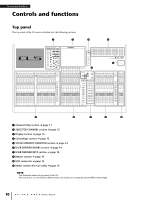
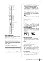
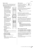
Controls and functions SELECTED CHANNEL section This section enables you to set the mix parameters for the currently-selected channel. 1 34 5 6 7 2 8 4 [PAN] knob When a monaural channel is selected, this knob adjusts the panning of the signal sent to the STEREO bus. When a stereo channel is selected, this knob adjusts the PAN or left/right balance, whichever is selected. 5 [DYNAMICS 1] knob 6 [DYNAMICS 2] knob Adjust the THRESHOLD parameter of the gate, compressor, etc. The [DYNAMICS 2] knob has no effect if the MIX, MATRIX, STEREO, or MONO channel is selected. 7 [HPF] knob Adjusts the HPF cutoff frequency for an input channel. It has no effect on other types of channels. 8 EQ [Q], EQ [FREQUENCY], EQ [GAIN] knobs For each band of the four-band EQ, these knobs adjust the Q, center frequency (cutoff frequency), and gain. Press the EQ [Q] and EQ [GAIN] knobs simultaneously to reset the GAIN setting for each band to the default value (0.0 dB). 1 [MIX1-16] key/[MIX17-24/MATRIX]key Select a MIX or MATRIX bus that is controlled by the knobs located below the keys. 2 [1]-[16] knobs Adjust the send level from currently-selected channels to the MIX or MATRIX bus. In SENDS ON FADER mode, push in a knob to select the corresponding destination bus. NOTE If the SIGNAL TYPE of the destination bus is set to STEREO, use the left knobs (odd-numbered channels) to adjust PAN and the right knobs (even-numbered channels) to adjust the send level. 3 [GAIN] knob Adjusts the head amp's analog gain for an input channel. On the other hand, it adjusts the digital gain if GAIN KNOB FUNCTION is set to DIGITAL GAIN in the PREFERENCE tab of the USER SETUP screen. This knob has no effect for other types of channels. NOTE • The PAD will be switched on or off internally when the HA analog gain is adjusted between +17 dB and +18 dB. Keep in mind that noise may be generated when using phantom power if there is a difference between the Hot and Cold output impedance of an external device connected to the INPUT connector. • The gain parameter value indicates the amount of amplification of the currently-input signal. Refer to the Conversion Table (page 11) for information on the relationship to conventional input sensitivity values. 12 Owner's Manual
-
 1
1 -
2
-
3
-
4
-
5
-
6
-
 7
7 -
 8
8 -
 9
9 -
 10
10 -
 11
11 -
 12
12 -
 13
13 -
 14
14 -
 15
15 -
 16
16 -
 17
17 -
18
-
19
-
20
-
21
-
22
-
23
-
24
-
25
-
26
-
27
-
28
-
29
-
30
-
31
-
32
-
33
-
34
-
35
-
36
-
37
-
38
-
39
-
40
-
41
-
42
-
43
-
44
-
45
-
46
-
47
-
48
-
49
-
50
-
51
-
52
-
53
-
54
-
55
-
56
-
57
-
58
-
59
-
60
-
61
-
62
-
63
-
64
-
65
 |
 |
