Yamaha CL3 Owner's Manual - Page 10
Controls and functions, Top panel - meter bridge
 |
View all Yamaha CL3 manuals
Add to My Manuals
Save this manual to your list of manuals |
Page 10 highlights
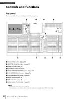
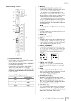
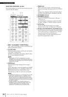
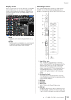
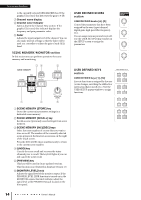
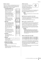
Controls and functions Controls and functions Top panel The top panel of the CL series is divided into the following sections. 2 3 6 j 9 5 1 4 7 1 8 1 Channel Strip section ➔ page 11 2 SELECTED CHANNEL section ➔ page 12 3 Display section ➔ page 13 4 Centralogic section ➔ page 13 5 SCENE MEMORY/MONITOR section ➔ page 14 6 USER DEFINED KNOBS section ➔ page 14 7 USER DEFINED KEYS section ➔ page 14 8 Master section ➔ page 15 9 USB connector ➔ page 15 0 Meter section (for CL5 only) ➔ page 15 NOTE This illustration shows the top panel of the CL5. The CL3 and CL1 do not feature a Meter section, but enable you to install an optional MBCL meter bridge. 10 Owner's Manual
-
 1
1 -
2
-
3
-
4
-
 5
5 -
 6
6 -
 7
7 -
 8
8 -
 9
9 -
 10
10 -
 11
11 -
 12
12 -
 13
13 -
 14
14 -
 15
15 -
16
-
17
-
18
-
19
-
20
-
21
-
22
-
23
-
24
-
25
-
26
-
27
-
28
-
29
-
30
-
31
-
32
-
33
-
34
-
35
-
36
-
37
-
38
-
39
-
40
-
41
-
42
-
43
-
44
-
45
-
46
-
47
-
48
-
49
-
50
-
51
-
52
-
53
-
54
-
55
-
56
-
57
-
58
-
59
-
60
-
61
-
62
-
63
-
64
-
65
 |
 |

Controls and functions
Owner’s Manual
10
Controls and functions
Top panel
The top panel of the CL series is divided into the following sections.
1
Channel Strip section
➔
page 11
2
SELECTED CHANNEL section
➔
page 12
3
Display section
➔
page 13
4
Centralogic section
➔
page 13
5
SCENE MEMORY/MONITOR section
➔
page 14
6
USER DEFINED KNOBS section
➔
page 14
7
USER DEFINED KEYS section
➔
page 14
8
Master section
➔
page 15
9
USB connector
➔
page 15
0
Meter section (for CL5 only)
➔
page 15
NOTE
This illustration shows the top panel of the CL5.
The CL3 and CL1 do not feature a Meter section, but enable you to install an optional MBCL meter bridge.
2
3
6
j
1
1
8
5
9
4
7