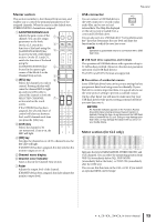
Yamaha CL3 Owner's Manual - Page 17
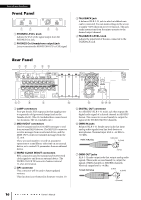
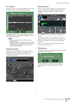
Dante connectors, NETWORK connector, SLOT 1-3, DC POWER INPUT connector, AC IN connector, Power Switch
 |
View all Yamaha CL3 manuals
Add to My Manuals
Save this manual to your list of manuals |
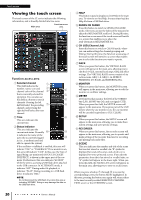
Page 17 highlights
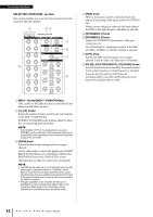
NOTE Although OMNI OUT jacks feature a nominal input/output level of +4 dBu (maximum level +24 dBu), an internal switch allows this to be changed to -2 dBu (maximum level +18 dBu) if necessary. (A fee will be charged for this procedure.) For details, contact your Yamaha dealer. 8 Dante connectors Used to connect to other Dante-compatible network devices, such as an Rio3224-D I/O rack. Use standard Ethernet cables with Neutrik EtherCon CAT5e compatible RJ-45 plugs. NOTE Use STP (shielded twisted pair) cable to prevent electromagnetic interference. Make sure that the metal parts of the plugs are electrically connected to the STP cable shield by conductive tape or comparable means. 9 NETWORK connector Allows the CL unit to be connected to a computer via an Ethernet cable (CAT5e or higher recommended). This connector is used mainly to control mix parameters or to edit scene memories and libraries from the dedicated "CL Editor" application program or "StageMix" iPad application. NOTE Use STP (shielded twisted pair) cable to prevent electromagnetic interference. Make sure that the metal parts of the plugs are electrically connected to the STP cable shield by conductive tape or comparable means. 0 SLOT 1-3 Allow for the installation of separately-sold DSP cards, or mini-YGDAI I/O cards to expand the number of input/output ports. A DC POWER INPUT connector You can connect the separately-sold PW800W power supply here as a backup external power supply. If the PW800W is connected, the CL unit will continue receiving power from the PW800W, even if its own internal power supply shuts down due to a problem. Caution If you plan to connect the PW800W, be sure to first power-off both the CL unit and the PW800W. Then, use the power supply cable (PSL360) to make the connection. Failure to observe this caution may cause malfunction or electric shock. NOTE • If a PW800W is connected, the CL series will operate correctly whether its own internal power supply and the PW800W are both turned on, or just one of them is turned on. • If both power supplies are turned on, and an abnormality is detected in one of the power supplies, the CL series will automatically switch to the other power supply. If this occurs, the touch screen will display a message to inform you. Rear Panel B AC IN connector Connect the supplied AC power cable here. First connect the AC power cable to the CL unit, then insert the power cable plug into an AC power outlet. The supplied AC power cable features a special latching mechanism (V-LOCK) to prevent the power cable from being disconnected accidentally. Connect the power cable by inserting the cable plug fully until it is locked. Caution Be sure to turn the power off before connecting or disconnecting the power cable. To disconnect the power cable, press the latch button on the plug. C (Power Switch) This switch turns power on or off. When the power switch is set to , the power to the unit is on. When the power switch is set to , the power to the unit is off. Caution • Rapidly turning the unit on and off in succession can cause it to malfunction. After turning the unit off, wait for at least 6 seconds before turning it on again. • Even when the power switch is turned off, a small amount of current is flowing through the unit. If you plan not to use the unit for a long period of time, remove the power cable from the AC outlet. D Grounding screw The supplied AC power cable is a 3-wire type. Therefore, if the AC outlet used is properly grounded, the CL will be grounded as well. Also, grounding this screw may effectively eliminate noise such as hum and interference. Owner's Manual 17
-
 1
1 -
2
-
3
-
4
-
5
-
6
-
7
-
8
-
9
-
10
-
11
-
 12
12 -
 13
13 -
 14
14 -
 15
15 -
 16
16 -
 17
17 -
 18
18 -
 19
19 -
 20
20 -
 21
21 -
 22
22 -
23
-
24
-
25
-
26
-
27
-
28
-
29
-
30
-
31
-
32
-
33
-
34
-
35
-
36
-
37
-
38
-
39
-
40
-
41
-
42
-
43
-
44
-
45
-
46
-
47
-
48
-
49
-
50
-
51
-
52
-
53
-
54
-
55
-
56
-
57
-
58
-
59
-
60
-
61
-
62
-
63
-
64
-
65
 |
 |