Yamaha CL3 Owner's Manual - Page 30
Adjusting the send level to a MIX bus or, MATRIX bus SENDS ON FADER mode, SENDS ON FADER button.
 |
View all Yamaha CL3 manuals
Add to My Manuals
Save this manual to your list of manuals |
Page 30 highlights
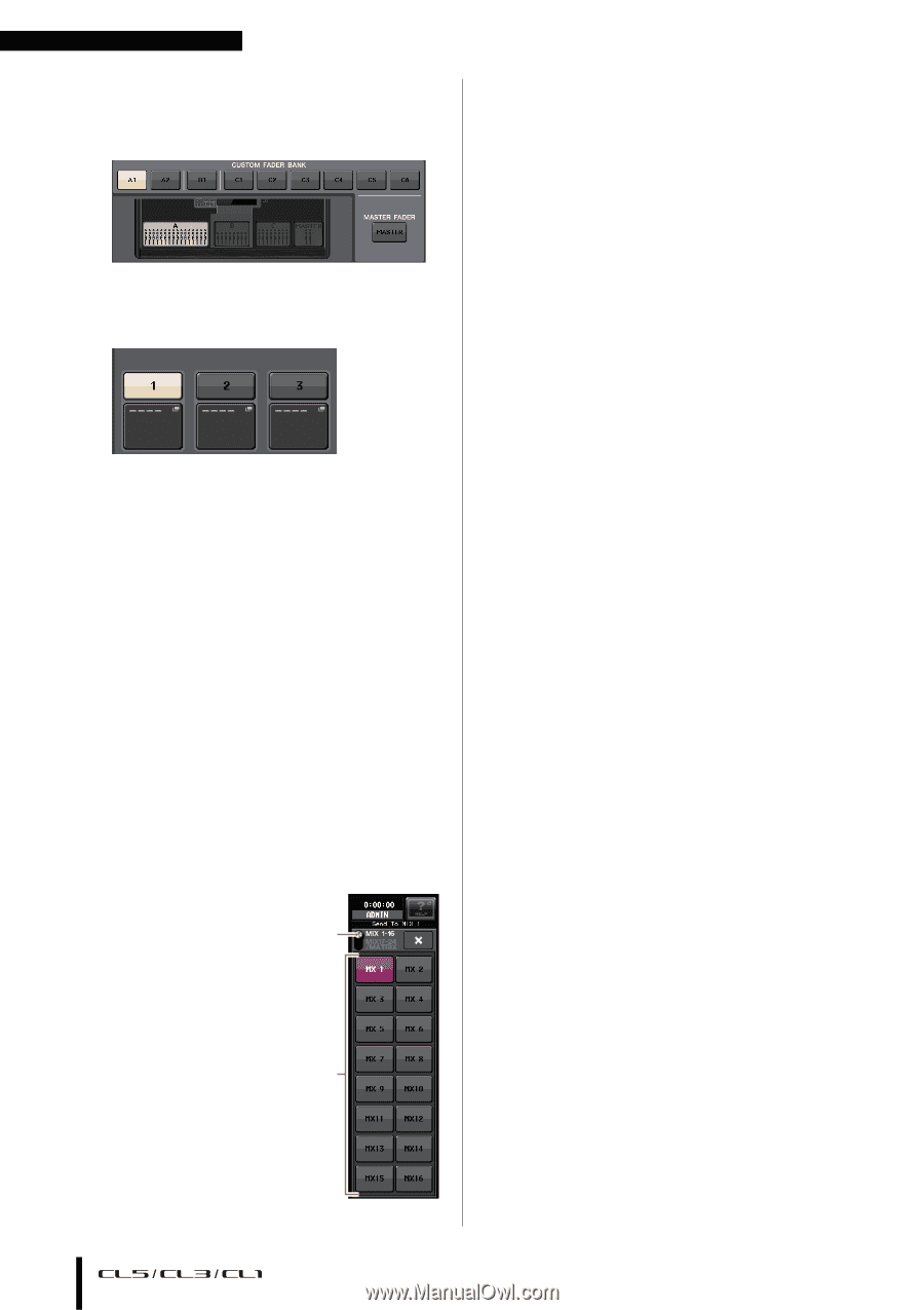
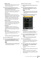
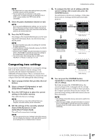
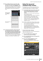
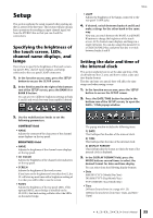
Basic operation of the CL series 4. Select a target custom fader bank. Channel strips are categorized into four blocks; from your left, block A, block B (Centralogic section), block C (only for CL5), and Master. 5. Press the number in the FADER area, then press the [SEL] key for the channel that you want to assign to that fader. You can also select a channel in the display. Press the button below the desired number to display the CH SELECT screen. First select the tab for a channel group, then select individual channels. To return to the previous screen, press the CLOSE button. 6. Repeat step 5 to select all channels that you want to assign to the custom fader bank. 7. When you have finished, press the X symbol in the upper right corner of the screen. Adjusting the send level to a MIX bus or MATRIX bus (SENDS ON FADER mode) Each fader on the top panel enables you to adjust the level of the corresponding channel, as well as the send level of the signal routed from each channel to the currently-selected MIX/MATRIX bus (SENDS ON FADER mode). Follow the procedure below to use the faders on the top panel to adjust a signal that is sent from all input channels to a specific MIX bus. 1. In the function access area in the display, press the SENDS ON FADER button. 1 The CL will switch to SENDS ON FADER mode. The most recently selected group of MIX/MATRIX buses will be assigned to the Centralogic section. The faders in the Channel Strip section will move to indicate the send level of the 2 signals that are routed from each channel to the currently-selected MIX/MATRIX bus. In SENDS ON FADER mode, the function access area in the display will show the button that enables you to switch between MIX1-16 and MIX17-24/MATRIX, and the buttons that enable you to select the destination MIX/MATRIX buses. 1 ON FADER switch button Pressing this button repeatedly will switch between MIX1-16 and MIX17-24/MATRIX. 2 MIX/MATRIX bus select buttons These buttons enable you to select the destination MIX/MATRIX buses. Two buses that are paired in stereo are represented by one button. 2. Press the ON FADER switch button repeatedly to select MIX1-16 or MIX17-24/MATRIX. In this way, you can use the MIX/MATRIX bus select buttons to specify the destination MIX/MATRIX buses. 3. Use the MIX or MATRIX bus select buttons in the function access area to select the send-destination MIX/MATRIX bus. NOTE • Alternatively, press a SEND LEVEL knob in the SELECTED CHANNEL section to display a popup window, from which you can select a MIX/MATRIX bus. • You can also select a MIX/MATRIX bus by using the Bank Select keys and the [SEL] keys in the Centralogic section. If you select the MIX buses or MATRIX buses by pressing the [SEL] keys, the setting of the MIX/MTRX ON FADER switch button will be changed automatically. • If you press the currently-selected MIX/MATRIX bus select button again, cue monitoring will be turned on for the related MIX/MATRIX channel. This method is convenient if you want to monitor the signal that is being sent to the selected MIX/MATRIX bus. 4. Use the faders in the INPUT section to adjust the send level from the input channels to the selected MIX/MATRIX bus. NOTE You can assign the SENDS ON FADER function to a USER DEFINED key. This lets you quickly switch to SENDS ON FADER mode for a specific MIX/MATRIX bus, and quickly switch back again. 5. Repeat steps 3-4 to adjust the send level for other MIX/MATRIX buses in the same way. 6. When you have finished adjusting the MIX/MATRIX send levels, press the X symbol in the function access area. The function access area display will return to its prior state, and the unit will return to normal mode. 30 Owner's Manual
-
 1
1 -
2
-
3
-
4
-
5
-
6
-
7
-
8
-
9
-
10
-
11
-
12
-
13
-
14
-
15
-
16
-
17
-
18
-
19
-
20
-
21
-
22
-
23
-
24
-
 25
25 -
 26
26 -
 27
27 -
 28
28 -
 29
29 -
 30
30 -
 31
31 -
 32
32 -
 33
33 -
 34
34 -
 35
35 -
36
-
37
-
38
-
39
-
40
-
41
-
42
-
43
-
44
-
45
-
46
-
47
-
48
-
49
-
50
-
51
-
52
-
53
-
54
-
55
-
56
-
57
-
58
-
59
-
60
-
61
-
62
-
63
-
64
-
65
 |
 |