Yamaha CL3 Owner's Manual - Page 11
Channel Strip GAIN/PAN/ASSIGN knob, SEL] key, CUE] key, Meter LEDs, ON] key
 |
View all Yamaha CL3 manuals
Add to My Manuals
Save this manual to your list of manuals |
Page 11 highlights
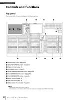
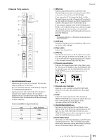
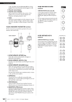
Channel Strip section 1 2 9 3 4 5 6 7 j 8 Top panel 2 [SEL] key Selects a channel that will be controlled in the Channel Strip section and on the touch screen. When a channel is selected, the key LED will light. If you control an ST IN channel in Block A of the Channel Strip section, the L channel will be routed to an odd-numbered channel, and the R channel will be routed to the adjacent even-numbered channel. If you control a channel in the CUSTOM bank or in Block C of the Channel Strip section, and if you assign L/R channels, the selected object of control will alternate between the L and R channels each time you press the [SEL] key. NOTE If you assign either the L or R channel, this key will simply select the channel. 3 [CUE] key Selects the channel to be cue-monitored. If the cue is on, the key LED will light. 4 Meter LEDs Indicate the channel level. 5 [ON] key Switches the channel on or off. If a channel is on, the key LED will light. In SENDS ON FADER mode, this is an on/off switch for signals sent from each channel to the currently-selected MIX/MATRIX bus. 6 Channel name display Indicates the channel name, knob value, fader value, etc. You can set the display so that it will indicate only the channel name. Use the PREFERENCE tab in the USER SETUP screen to select information to be displayed. 1 GAIN/PAN/ASSIGN knob Adjusts the gain or pan of the channel. You can also assign a parameter to this knob. You can switch the function of the knob by using the 9 [GAIN/PAN/ASSIGN] key. A gain parameter value indicated on the display or channel name display indicates the amount of amplification of a currently-input signal. Refer to the Conversion Table for information on the relationship to input sensitivity. Conversion Table for Input Sensitivity Gain -6dB : 0 : +66dB Input Sensitivity +10dBu : +4dBu : -62dBu 7 Channel color indicator Lights in a color specified on the PATCH/NAME screen. You can select the channel color from eight options. 8 Fader Adjusts the input/output level of the channel. In SENDS ON FADER mode, this fader adjusts the send level of the signal from each channel to the currently-selected MIX/MATRIX bus. 9 [GAIN/PAN/ASSIGN] key Switches the knob function for each block on the channel strip. The LED for the selected function will light. Use the USER DEFINED KNOBS tab in the USER SETUP screen to select a parameter to control when the ASSIGN function is selected. 0 Bank Select keys These keys switch the channel faders controlled in the Channel Strip section. The [CUSTOM] keys enable you to select your own custom fader bank. For details on the custom fader banks, refer to page 47. Owner's Manual 11
-
 1
1 -
2
-
3
-
4
-
5
-
 6
6 -
 7
7 -
 8
8 -
 9
9 -
 10
10 -
 11
11 -
 12
12 -
 13
13 -
 14
14 -
 15
15 -
 16
16 -
17
-
18
-
19
-
20
-
21
-
22
-
23
-
24
-
25
-
26
-
27
-
28
-
29
-
30
-
31
-
32
-
33
-
34
-
35
-
36
-
37
-
38
-
39
-
40
-
41
-
42
-
43
-
44
-
45
-
46
-
47
-
48
-
49
-
50
-
51
-
52
-
53
-
54
-
55
-
56
-
57
-
58
-
59
-
60
-
61
-
62
-
63
-
64
-
65
 |
 |
