Yamaha CL3 Owner's Manual - Page 20
Viewing the touch screen, Function access area - case
 |
View all Yamaha CL3 manuals
Add to My Manuals
Save this manual to your list of manuals |
Page 20 highlights
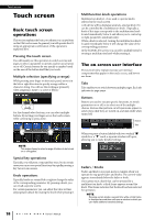
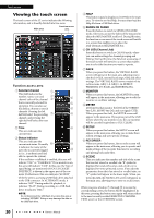
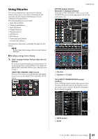
Touch screen Viewing the touch screen The touch screen of the CL series indicates the following information, and is broadly divided into two areas. Main area Function access area Function access area 1 Selected channel 1 This field indicates the number, name, icon and 2 channel color of the channel 3 4 that is currently selected for 5 operation. You can also use this field as a button to switch 6 channels. Pressing the left half will select the preceding 7 8 channel, and pressing the right half will select the next channel. 2 Time 9 This area indicates the current time. 3 Status Indicator This area indicates the current unit status. Normally j k it indicates the name of the user who is currently logged l in (i.e., is authenticated and able to operate the system). If the oscillator or talkback is enabled, this area will indicate "OSC" or "TALKBACK." If cue monitor is on, this area will indicate "CUE." In this case, the type of signal being cue-monitored (IN/OUT/DCA/KEY IN/EFFECT) is shown in the upper part of the cue meter. Furthermore, this area indicates "ACCESS" while the unit is accessing a USB flash drive attached to the USB connector. In ALTERNATE mode, it indicates "ALT." During audio file playback, it indicates "PLAY." During recording to a USB flash drive, it indicates "REC." NOTE Do not disconnect the USB flash drive while this area is indicating "ACCESS." Doing so may damage the data on the USB flash drive. 4 HELP This button is used to display on-line Help in the main area. To view the on-line Help, first you must load the Help file from a USB flash drive. 5 SENDS ON FADER Press this button to switch to SENDS ON FADER mode, where you can use the faders of the top panel to adjust the MIX/MATRIX send level. During this time, the function access area of the touch screen will switch to a screen that enables you to select the send-destination MIX/MATRIX bus. 6 CH JOB (Channel Job) Press this button to switch to CH JOB mode, where you can make settings for channel grouping and linking. During this time, the function access area of the touch screen will switch to a screen that enables you to select the function you want to operate. 7 RACK When you press this button, the VIRTUAL RACK screen will appear in the main area, allowing you to edit the I/O rack, external head amps, GEQ and effect settings. The VIRTUAL RACK screen consists of six rack sections: GEQ 1-8, GEQ 9-16, EFFECT, PREMIUM, I/O RACK, and EXTERNAL HA. 8 MONITOR When you press this button, the MONITOR screen will appear in the main area, allowing you to edit the monitor or oscillator settings. 9 METER Level meters that monitor the level of the STEREO bus (L/R), MONO bus (M), and cue signal (CUE). When you press this field, the METER screen will appear in the main area. If you press part of the CUE meters when the cue monitor is on, the cue monitor will be canceled (equivalent to CUE CLEAR). 0 SETUP When you press this button, the SETUP screen will appear in the main area, allowing you to make basic system settings and user-specific settings. A RECORDER When you press this button, the recorder screen will appear in the main area, allowing you to operate and make settings of the recorder function for recording and playing back audio files. B SCENE This area indicates the number and title of the scene that was last stored or recalled. An "R" symbol is displayed for read-only scenes, and a lock icon is displayed for write-protected scenes. If you edit the parameters from their last stored or recalled state, an "E" symbol will appear in the lower right. When you press this field, the SCENE LIST screen will appear in the main area, allowing you to store or recall scenes. When you press a button 7 through B to access the corresponding screen, the button will be highlighted. In this state, pressing the button once again will return either to the most recently recalled SELECTED CHANNEL VIEW screen or the OVERVIEW screen. 20 Owner's Manual
-
 1
1 -
2
-
3
-
4
-
5
-
6
-
7
-
8
-
9
-
10
-
11
-
12
-
13
-
14
-
 15
15 -
 16
16 -
 17
17 -
 18
18 -
 19
19 -
 20
20 -
 21
21 -
 22
22 -
 23
23 -
 24
24 -
 25
25 -
26
-
27
-
28
-
29
-
30
-
31
-
32
-
33
-
34
-
35
-
36
-
37
-
38
-
39
-
40
-
41
-
42
-
43
-
44
-
45
-
46
-
47
-
48
-
49
-
50
-
51
-
52
-
53
-
54
-
55
-
56
-
57
-
58
-
59
-
60
-
61
-
62
-
63
-
64
-
65
 |
 |
