Adaptec 1966600 User Guide - Page 17
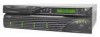
SCSI RAID Appliance I/O Connectivity Panel, system Host Bus Adapters HBAs to the DuraStor SCSI RAID
 |
UPC - 760884139202
View all Adaptec 1966600 manuals
Add to My Manuals
Save this manual to your list of manuals |
Page 17 highlights
About the DuraStor Storage Subsystem processor monitors the temperature and reports when this condition occurs.) If a fan fails, the Fault LED lights up. Failed cooling fans must be replaced immediately. The cooling fan module can be hot-swapped during normal operation. See Replacing the Cooling Fan Module on page 5-4 for more details. ! Caution: Do not operate the DuraStor RAID appliance for longer than 5 minutes with the cooling fan module removed. Cooling is unavailable to all components while the fans are removed. SCSI RAID Appliance I/O Connectivity Panel The I/O connectivity panel of the SCSI RAID appliance connects the host computer (server) to the storage enclosure disk drives. See Figure 2-9 for detailed connection information. Connects to Host System or to Storage Enclosure I/O Card HOST 1 IN (CH 3) HOST 2 IN (CH 0) DISK CH 2 DISK CH 1 Connects to Storage Enclosure I/O Card Connects to Host System Connect to Host System or to Host In via Jumper Cable HOST 1 OUT HOST 2 OUT Switches Mode from OCP (INT) to SERIAL B SERIAL A Ext VT-100 Terminal Int (EXT) Connects to External VT-100 Terminal Connects to External VT-100 Terminal Figure 2-9. SCSI RAID Appliance I/O Connectivity Panel Four 68-pin very-high-density SCSI connectors connect the host system Host Bus Adapters (HBAs) to the DuraStor SCSI RAID controller host channels. From left to right: s Host 1 In (CH 3) s Host 2 In (CH 0) s Host 1 Out s Host 2 Out 2-7
-
 1
1 -
2
-
3
-
4
-
5
-
6
-
7
-
8
-
9
-
10
-
11
-
 12
12 -
 13
13 -
 14
14 -
 15
15 -
 16
16 -
 17
17 -
 18
18 -
 19
19 -
 20
20 -
 21
21 -
 22
22 -
23
-
24
-
25
-
26
-
27
-
28
-
29
-
30
-
31
-
32
-
33
-
34
-
35
-
36
-
37
-
38
-
39
-
40
-
41
-
42
-
43
-
44
-
45
-
46
-
47
-
48
-
49
-
50
-
51
-
52
-
53
-
54
-
55
-
56
-
57
-
58
-
59
-
60
-
61
-
62
-
63
-
64
-
65
-
66
-
67
-
68
-
69
-
70
-
71
-
72
-
73
-
74
-
75
-
76
-
77
-
78
-
79
-
80
-
81
-
82
-
83
-
84
-
85
-
86
-
87
-
88
-
89
-
90
-
91
-
92
-
93
-
94
-
95
-
96
-
97
-
98
-
99
-
100
-
101
-
102
-
103
-
104
-
105
-
106
-
107
-
108
-
109
-
110
-
111
-
112
-
113
-
114
-
115
-
116
-
117
-
118
-
119
-
120
-
121
-
122
-
123
-
124
-
125
-
126
-
127
-
128
-
129
-
130
-
131
-
132
-
133
 |
 |
