Adaptec 1966600 User Guide - Page 18
Host 1 In CH 3, Disk CH 2, and, Controller 1; Serial B port is for Controller 2.
 |
UPC - 760884139202
View all Adaptec 1966600 manuals
Add to My Manuals
Save this manual to your list of manuals |
Page 18 highlights
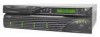
DuraStor 6220SS/7220SS Installation and User's Guide Additionally, two 68-pin very-high-density SCSI connectors connect to the disk channels of the DuraStor 312R storage enclosure. From left to right: s Disk CH 2 s Disk CH 1 The connector labeled Host In (CH 3) can also be used as a disk channel under some configurations. See Appendix A, Port Information for connector pin-out detail. Two RS-232 serial ports each connect a controller to a VT-100 terminal, and are used when you want to access Disk Array Administrator management software. Serial A port is for Controller 1; Serial B port is for Controller 2. Note: Host 1 In (CH 3), Host 2 In (CH 0), Disk CH 2, and Disk CH 1 ports require external termination when they are unused in any dual-controller (active-active or activepassive) configuration. The single-controller (stand-alone) configuration requires no external terminators. Host 1 Out and Host 2 Out have automatic internal termination when they are unused. The switch in the lower right corner of the panel sets the keyboard/keypad input control to either INT (internal, via the OCP) or EXT (external, via the VT-100 keyboard or a computer running Hyper Terminal). Setting the switch to EXT disables the OCP buttons. Note: The front bezel LEDs will work whether the OCP is being used or not. Setting this switch to EXT will not disable the front bezel LEDs. Table 2-1 summarizes the specific technical specifications of the DuraStor SCSI RAID appliance. 2-8
-
 1
1 -
2
-
3
-
4
-
5
-
6
-
7
-
8
-
9
-
10
-
11
-
12
-
 13
13 -
 14
14 -
 15
15 -
 16
16 -
 17
17 -
 18
18 -
 19
19 -
 20
20 -
 21
21 -
 22
22 -
 23
23 -
24
-
25
-
26
-
27
-
28
-
29
-
30
-
31
-
32
-
33
-
34
-
35
-
36
-
37
-
38
-
39
-
40
-
41
-
42
-
43
-
44
-
45
-
46
-
47
-
48
-
49
-
50
-
51
-
52
-
53
-
54
-
55
-
56
-
57
-
58
-
59
-
60
-
61
-
62
-
63
-
64
-
65
-
66
-
67
-
68
-
69
-
70
-
71
-
72
-
73
-
74
-
75
-
76
-
77
-
78
-
79
-
80
-
81
-
82
-
83
-
84
-
85
-
86
-
87
-
88
-
89
-
90
-
91
-
92
-
93
-
94
-
95
-
96
-
97
-
98
-
99
-
100
-
101
-
102
-
103
-
104
-
105
-
106
-
107
-
108
-
109
-
110
-
111
-
112
-
113
-
114
-
115
-
116
-
117
-
118
-
119
-
120
-
121
-
122
-
123
-
124
-
125
-
126
-
127
-
128
-
129
-
130
-
131
-
132
-
133
 |
 |
