Canon EOS C500 Instruction Manual - Page 91
Time Code Signal Output, 3G-SDI terminals, MON. terminals and HD/SD SDI terminal.
 |
View all Canon EOS C500 manuals
Add to My Manuals
Save this manual to your list of manuals |
Page 91 highlights
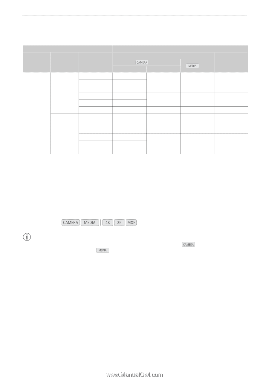
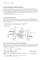
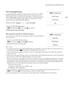
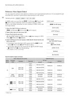
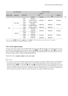
Synchronizing with an External Device Video configuration SYNC OUT terminal HD Sync1 System priority Resolution Frame rate Normal2 mode XF Legacy Blk Burst mode 91 59.94i 1080/59.94i 29.97P 1080/29.97 (P/PsF) 1080/59.94i 1080/59.94i 480/59.94i 1920×1080 23.98P 50.00i 25.00P 1080/23.98 (P/PsF) 1080/50.00i 1080/25.00 (P/PsF) 1080/50.00i 1080/50.00i 576/50.00i 24.00P 1080/24.00 (P/PsF) 1080/60.00i 1080/60.00i - MXF 59.94P 720/59.94P 29.97P 720/29.97P 720/59.94P 720/59.94P 480/59.94i 1280×720 23.98P 50.00P 25.00P 720/23.98P 720/50.00P 720/25.00P 720/50.00P 720/50.00P 576/50.00i 24.00P 720/24.00P 720/60.00P 720/60.00P - 1 You can use the [¤ TC/UB Setup ] > [Time Code] > [24P TC/Sync] setting to select [Normal] or [XF Legacy]. 2 You can switch between the P and PsF setting for output. Time Code Signal Output The time code will be output from the TIME CODE terminal as an SMPTE-standard LTC timing signal. The user bit will also be output. Before connecting the device, set [¤ TC/UB Setup] > [Time Code] > [TC In/Out] to [Out] to change the TIME CODE terminal to output (A 89). The embedded time code will be output from the 3G-SDI terminals, MON. terminals and HD/SD SDI terminal. Operating modes: NOTES • The user bit of the time code signal is output while the camera is recording in mode or during playback of a clip recorded on a CF card in mode. For the HD/SD SDI terminal, when the frame rate is set to [23.98P] and the [¤ TC/UB Setup] > [User Bit] > [Output Mode] setting is set to [Pulldown], the user bit will be 2:3 pulldown data. In other words, when a 23.98P recording is output from the HD/SD SDI terminal, the signal is converted to 59.94i using the 2:3 pulldown method. An external device can receive the data used in this conversion (2:3 pulldown data) to convert the signal to the original 23.98P specifications.
-
 1
1 -
2
-
3
-
4
-
5
-
6
-
7
-
8
-
9
-
10
-
11
-
12
-
13
-
14
-
15
-
16
-
17
-
18
-
19
-
20
-
21
-
22
-
23
-
24
-
25
-
26
-
27
-
28
-
29
-
30
-
31
-
32
-
33
-
34
-
35
-
36
-
37
-
38
-
39
-
40
-
41
-
42
-
43
-
44
-
45
-
46
-
47
-
48
-
49
-
50
-
51
-
52
-
53
-
54
-
55
-
56
-
57
-
58
-
59
-
60
-
61
-
62
-
63
-
64
-
65
-
66
-
67
-
68
-
69
-
70
-
71
-
72
-
73
-
74
-
75
-
76
-
77
-
78
-
79
-
80
-
81
-
82
-
83
-
84
-
85
-
 86
86 -
 87
87 -
 88
88 -
 89
89 -
 90
90 -
 91
91 -
 92
92 -
 93
93 -
 94
94 -
 95
95 -
 96
96 -
97
-
98
-
99
-
100
-
101
-
102
-
103
-
104
-
105
-
106
-
107
-
108
-
109
-
110
-
111
-
112
-
113
-
114
-
115
-
116
-
117
-
118
-
119
-
120
-
121
-
122
-
123
-
124
-
125
-
126
-
127
-
128
-
129
-
130
-
131
-
132
-
133
-
134
-
135
-
136
-
137
-
138
-
139
-
140
-
141
-
142
-
143
-
144
-
145
-
146
-
147
-
148
-
149
-
150
-
151
-
152
-
153
-
154
-
155
-
156
-
157
-
158
-
159
-
160
-
161
-
162
-
163
-
164
-
165
-
166
-
167
-
168
-
169
-
170
-
171
-
172
-
173
-
174
-
175
-
176
-
177
-
178
-
179
-
180
-
181
-
182
-
183
-
184
-
185
-
186
-
187
-
188
-
189
-
190
-
191
-
192
-
193
-
194
-
195
-
196
-
197
-
198
-
199
-
200
-
201
-
202
-
203
-
204
-
205
-
206
-
207
-
208
-
209
-
210
-
211
-
212
 |
 |