Cisco PVC300 Administration Guide - Page 10
Digital Input Digital Output Diagram, Getting to Know the PVC300 PTZ Internet Camera, Status LED Color
 |
UPC - 745883584505
View all Cisco PVC300 manuals
Add to My Manuals
Save this manual to your list of manuals |
Page 10 highlights
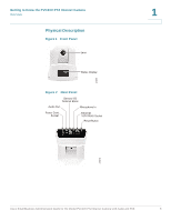
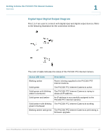
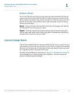
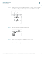
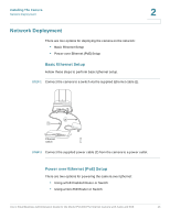
Getting to Know the PVC300 PTZ Internet Camera Overview 1 Digital Input Digital Output Diagram Pins 1 to 4 are used to connect with digital input and digital output devices. Refer to the following illustration for the connection method. The color of LEDs indicates the status of the PVC300 PTZ Internet Camera. Status LED Color Description Blinking amber Power is being supplied to the PVC300 PTZ Internet Camera. Solid green The PVC300 PTZ Internet Camera is active. Solid green with blinking The PVC300 PTZ Internet Camera is trying to amber in between obtain an IP address. Solid green and amber An IP address is successfully assigned to the PVC300 PTZ Internet Camera. Solid amber with blinking The PVC300 PTZ Internet Camera is working. green in between Blinking amber and green The PVC300 PTZ Internet Camera is performing a firmware upgrade. Cisco Small Business Administration Guide for the Model PVC300 PTZ Internet Camera with Audio and PoE 10
-
 1
1 -
2
-
3
-
4
-
 5
5 -
 6
6 -
 7
7 -
 8
8 -
 9
9 -
 10
10 -
 11
11 -
 12
12 -
 13
13 -
 14
14 -
 15
15 -
16
-
17
-
18
-
19
-
20
-
21
-
22
-
23
-
24
-
25
-
26
-
27
-
28
-
29
-
30
-
31
-
32
-
33
-
34
-
35
-
36
-
37
-
38
-
39
-
40
-
41
-
42
-
43
-
44
-
45
-
46
-
47
-
48
-
49
-
50
-
51
-
52
-
53
-
54
-
55
-
56
-
57
-
58
-
59
-
60
-
61
-
62
-
63
-
64
-
65
-
66
-
67
-
68
-
69
 |
 |
