Dell PowerConnect Brocade M6505 Brocade 7.1.0 Fabric Watch Administrator's Gui - Page 63
SFP monitoring guidelines and default settings, SFP class areas
 |
View all Dell PowerConnect Brocade M6505 manuals
Add to My Manuals
Save this manual to your list of manuals |
Page 63 highlights
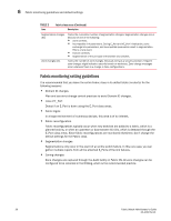
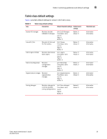
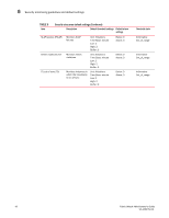
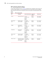
SFP monitoring guidelines and default settings 6 SFP monitoring guidelines and default settings The SFP class groups areas that monitor the physical aspects of SFPs. An SFP class alarm alerts you to an SFP malfunction fault. SFP performance monitoring is not supported on VE_Ports. When a port goes offline, the RXP and TXP area values of the SFP become zero. Brocade recommends non-zero low thresholds for RXP and TXP; therefore, Fabric Watch stops monitoring RXP and TXP parameters of the SFP once the port goes offline. SFP class areas Table 7 lists Product Name areas in the SFP class and describes each area. Although it is recommended that you leave the entire SFP class in its default state (no alerts), you can configure the SFP class using the thConfig command. NOTE SFPs connected to GbE ports are not monitored. TABLE 7 Area SFP class areas Description Temperature Receive power (RXP) Transmit power (TXP) Current Voltage Measures the physical temperature of the SFP, in degrees Celsius. A high temperature indicates that the SFP might be in danger of damage. Measures the amount of incoming laser, in µwatts, to help determine if the SFP is in good working condition. If the counter often exceeds the threshold, the SFP is deteriorating. Measures the amount of outgoing laser, in µwatts. Use this to determine the condition of the SFP. If the counter often exceeds the threshold, the SFP is deteriorating. Measures the amount of supplied current to the SFP transceiver. Current area events indicate hardware failures. Measures the amount of voltage supplied to the SFP. If this value exceeds the threshold, the SFP is deteriorating. Fabric Watch Administrator's Guide 43 53-1002752-01
-
 1
1 -
2
-
3
-
4
-
5
-
6
-
7
-
8
-
9
-
10
-
11
-
12
-
13
-
14
-
15
-
16
-
17
-
18
-
19
-
20
-
21
-
22
-
23
-
24
-
25
-
26
-
27
-
28
-
29
-
30
-
31
-
32
-
33
-
34
-
35
-
36
-
37
-
38
-
39
-
40
-
41
-
42
-
43
-
44
-
45
-
46
-
47
-
48
-
49
-
50
-
51
-
52
-
53
-
54
-
55
-
56
-
57
-
 58
58 -
 59
59 -
 60
60 -
 61
61 -
 62
62 -
 63
63 -
 64
64 -
 65
65 -
 66
66 -
 67
67 -
 68
68 -
69
-
70
-
71
-
72
-
73
-
74
-
75
-
76
-
77
-
78
-
79
-
80
-
81
-
82
-
83
-
84
-
85
-
86
-
87
-
88
-
89
-
90
-
91
-
92
-
93
-
94
-
95
-
96
-
97
-
98
-
99
-
100
-
101
-
102
-
103
-
104
-
105
-
106
-
107
-
108
-
109
-
110
-
111
-
112
-
113
-
114
-
115
-
116
-
117
-
118
-
119
-
120
-
121
-
122
-
123
-
124
-
125
-
126
 |
 |