HP 2420 Service Manual - Page 134
Gear assembly, Covers, Control, panel, Formatter, Right-side, handle
 |
UPC - 829160289205
View all HP 2420 manuals
Add to My Manuals
Save this manual to your list of manuals |
Page 134 highlights
Gear assembly 1. Remove all of the covers (see Covers). 2. Remove the control panel (see Control panel). 3. Remove the formatter (see Formatter). 4. Remove the right-side handle (see Right-side handle). 5. Remove the ECU (see ECU). 6. Remove the two screws (callout 1) that secure the right-side fan to the printer chassis, and then lift the fan away from the printer. Figure 6-41. NOTE Removing the gear assembly (1 of 6) 7. Before removing the air duct, examine the cable routing around and through the air duct. Make sure that you duplicate the cable routing upon reinstallation. 120 Chapter 6 Removal and replacement ENWW
-
 1
1 -
2
-
3
-
4
-
5
-
6
-
7
-
8
-
9
-
10
-
11
-
12
-
13
-
14
-
15
-
16
-
17
-
18
-
19
-
20
-
21
-
22
-
23
-
24
-
25
-
26
-
27
-
28
-
29
-
30
-
31
-
32
-
33
-
34
-
35
-
36
-
37
-
38
-
39
-
40
-
41
-
42
-
43
-
44
-
45
-
46
-
47
-
48
-
49
-
50
-
51
-
52
-
53
-
54
-
55
-
56
-
57
-
58
-
59
-
60
-
61
-
62
-
63
-
64
-
65
-
66
-
67
-
68
-
69
-
70
-
71
-
72
-
73
-
74
-
75
-
76
-
77
-
78
-
79
-
80
-
81
-
82
-
83
-
84
-
85
-
86
-
87
-
88
-
89
-
90
-
91
-
92
-
93
-
94
-
95
-
96
-
97
-
98
-
99
-
100
-
101
-
102
-
103
-
104
-
105
-
106
-
107
-
108
-
109
-
110
-
111
-
112
-
113
-
114
-
115
-
116
-
117
-
118
-
119
-
120
-
121
-
122
-
123
-
124
-
125
-
126
-
127
-
128
-
 129
129 -
 130
130 -
 131
131 -
 132
132 -
 133
133 -
 134
134 -
 135
135 -
 136
136 -
 137
137 -
 138
138 -
 139
139 -
140
-
141
-
142
-
143
-
144
-
145
-
146
-
147
-
148
-
149
-
150
-
151
-
152
-
153
-
154
-
155
-
156
-
157
-
158
-
159
-
160
-
161
-
162
-
163
-
164
-
165
-
166
-
167
-
168
-
169
-
170
-
171
-
172
-
173
-
174
-
175
-
176
-
177
-
178
-
179
-
180
-
181
-
182
-
183
-
184
-
185
-
186
-
187
-
188
-
189
-
190
-
191
-
192
-
193
-
194
-
195
-
196
-
197
-
198
-
199
-
200
-
201
-
202
-
203
-
204
-
205
-
206
-
207
-
208
-
209
-
210
-
211
-
212
-
213
-
214
-
215
-
216
-
217
-
218
-
219
-
220
-
221
-
222
-
223
-
224
-
225
-
226
-
227
-
228
-
229
-
230
-
231
-
232
-
233
-
234
-
235
-
236
-
237
-
238
-
239
-
240
-
241
-
242
-
243
-
244
-
245
-
246
-
247
-
248
-
249
-
250
-
251
-
252
-
253
-
254
-
255
-
256
-
257
-
258
-
259
-
260
-
261
-
262
-
263
-
264
-
265
-
266
-
267
-
268
-
269
-
270
-
271
-
272
-
273
-
274
-
275
-
276
-
277
-
278
-
279
-
280
-
281
-
282
-
283
-
284
-
285
-
286
-
287
-
288
-
289
-
290
-
291
-
292
-
293
-
294
 |
 |

Gear assembly
1.
Remove all of the covers (see
Covers
).
2.
Remove the control panel (see
Control
panel
).
3.
Remove the formatter (see
Formatter
).
4.
Remove the right-side handle (see
Right-side
handle
).
5.
Remove the ECU (see
ECU
).
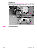
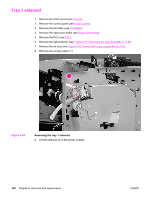
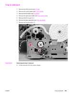
6.
Remove the two screws (callout 1) that secure the right-side fan to the printer chassis,
and then lift the fan away from the printer.
Figure 6-41.
Removing the gear assembly (1 of 6)
7.
Before removing the air duct, examine the cable routing around and through the air duct.
NOTE
Make sure that you duplicate the cable routing upon reinstallation.
120
Chapter 6
Removal and replacement
ENWW