HP 2420 Service Manual - Page 136
Removing the gear assembly 3 of 6
 |
UPC - 829160289205
View all HP 2420 manuals
Add to My Manuals
Save this manual to your list of manuals |
Page 136 highlights
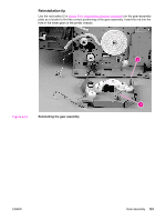
10. Remove four screws (callout 3) from the gear-assembly plate. 3 4 Figure 6-43. NOTE Removing the gear assembly (3 of 6) 11. Pull the gear assembly straight away from the printer. The spring (callout 1 in Figure 6-44. Reinstalling the gear assembly) is not attached to the gear-assembly plate or to the large gear. As a result, the spring might fall out of the printer when you remove the gear assembly. Reinstallation tip Close the cartridge door and press the large gear against the printer chassis before you start to reinstall the gear assembly. Reinstallation tip The spring has a locator pin that should be inserted into the small hole in the gear-assembly plate before reinstallation. 122 Chapter 6 Removal and replacement ENWW
-
 1
1 -
2
-
3
-
4
-
5
-
6
-
7
-
8
-
9
-
10
-
11
-
12
-
13
-
14
-
15
-
16
-
17
-
18
-
19
-
20
-
21
-
22
-
23
-
24
-
25
-
26
-
27
-
28
-
29
-
30
-
31
-
32
-
33
-
34
-
35
-
36
-
37
-
38
-
39
-
40
-
41
-
42
-
43
-
44
-
45
-
46
-
47
-
48
-
49
-
50
-
51
-
52
-
53
-
54
-
55
-
56
-
57
-
58
-
59
-
60
-
61
-
62
-
63
-
64
-
65
-
66
-
67
-
68
-
69
-
70
-
71
-
72
-
73
-
74
-
75
-
76
-
77
-
78
-
79
-
80
-
81
-
82
-
83
-
84
-
85
-
86
-
87
-
88
-
89
-
90
-
91
-
92
-
93
-
94
-
95
-
96
-
97
-
98
-
99
-
100
-
101
-
102
-
103
-
104
-
105
-
106
-
107
-
108
-
109
-
110
-
111
-
112
-
113
-
114
-
115
-
116
-
117
-
118
-
119
-
120
-
121
-
122
-
123
-
124
-
125
-
126
-
127
-
128
-
129
-
130
-
 131
131 -
 132
132 -
 133
133 -
 134
134 -
 135
135 -
 136
136 -
 137
137 -
 138
138 -
 139
139 -
 140
140 -
 141
141 -
142
-
143
-
144
-
145
-
146
-
147
-
148
-
149
-
150
-
151
-
152
-
153
-
154
-
155
-
156
-
157
-
158
-
159
-
160
-
161
-
162
-
163
-
164
-
165
-
166
-
167
-
168
-
169
-
170
-
171
-
172
-
173
-
174
-
175
-
176
-
177
-
178
-
179
-
180
-
181
-
182
-
183
-
184
-
185
-
186
-
187
-
188
-
189
-
190
-
191
-
192
-
193
-
194
-
195
-
196
-
197
-
198
-
199
-
200
-
201
-
202
-
203
-
204
-
205
-
206
-
207
-
208
-
209
-
210
-
211
-
212
-
213
-
214
-
215
-
216
-
217
-
218
-
219
-
220
-
221
-
222
-
223
-
224
-
225
-
226
-
227
-
228
-
229
-
230
-
231
-
232
-
233
-
234
-
235
-
236
-
237
-
238
-
239
-
240
-
241
-
242
-
243
-
244
-
245
-
246
-
247
-
248
-
249
-
250
-
251
-
252
-
253
-
254
-
255
-
256
-
257
-
258
-
259
-
260
-
261
-
262
-
263
-
264
-
265
-
266
-
267
-
268
-
269
-
270
-
271
-
272
-
273
-
274
-
275
-
276
-
277
-
278
-
279
-
280
-
281
-
282
-
283
-
284
-
285
-
286
-
287
-
288
-
289
-
290
-
291
-
292
-
293
-
294
 |
 |

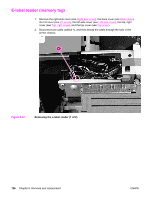
10.
Remove four screws (callout 3) from the gear-assembly plate.
3
4
Figure 6-43.
Removing the gear assembly (3 of 6)
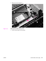
11.
Pull the gear assembly straight away from the printer.
NOTE
The spring (callout 1 in
Figure
6-44.
Reinstalling
the
gear
assembly
) is not attached to the
gear-assembly plate or to the large gear. As a result, the spring might fall out of the printer
when you remove the gear assembly.
Reinstallation tip
Close the cartridge door and press the large gear against the printer chassis before you start
to reinstall the gear assembly.
Reinstallation tip
The spring has a locator pin that should be inserted into the small hole in the gear-assembly
plate before reinstallation.
122
Chapter 6
Removal and replacement
ENWW