HP NetServer AA 4000 HP Netserver AA Solution Installation Guide v4.0 SP1 - Page 35
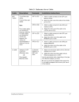
Table 2-1, Endurance Server Cables, Cable, Description, Connects, Installation Instructions
 |
View all HP NetServer AA 4000 manuals
Add to My Manuals
Save this manual to your list of manuals |
Page 35 highlights
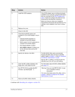
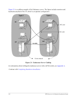
Table 2-1 Endurance Server Cables Cable Description Connects Installation Instructions MIC Cables 2 local fiber optic cables 2 remote fiber optic cables IOP1 to CE1 Note: IOP2 to CE2 The 5 meter cables are intended for local use, while the 10 meter cables are intended for remote use. However, the cables are interchangeable if distance is not an issue. IOP1 to CE2 IOP2 to CE1 IL Cable Category 5 UTP cross-over (Ethernet) cable OR Fiber (gigabit Ethernet) cable IL Ethernet adapters on IOP1 and IOP2 1. Attach a cable connector to the IOP1 port labeled LOCAL. 2. Attach the other end of the cable to the LOCAL port on CE1. 1. Attach a cable connector to the IOP2 port labeled LOCAL. 2. Attach the other end of the cable to the LOCAL port on CE2. 1. Attach a cable connector to the IOP1 port labeled REMOTE. 2. Attach the other end of the cable to the REMOTE port on CE2. 1. Attach a cable connector to the IOP2 port labeled REMOTE. 2. Attach the other end of the cable to the REMOTE port on CE1. 1. Attach one end of the cable to the IL Ethernet adapter port on IOP1. 2. Attach the other end of the cable to the IL Ethernet adapter port on IOP2. Use the appropriate cable, depending on the type of IL Ethernet adapter you have. Be sure to connect the adapters that support the IL and not the adapters that connect your server to the network. Installing the Hardware 2-7
-
 1
1 -
2
-
3
-
4
-
5
-
6
-
7
-
8
-
9
-
10
-
11
-
12
-
13
-
14
-
15
-
16
-
17
-
18
-
19
-
20
-
21
-
22
-
23
-
24
-
25
-
26
-
27
-
28
-
29
-
 30
30 -
 31
31 -
 32
32 -
 33
33 -
 34
34 -
 35
35 -
 36
36 -
 37
37 -
 38
38 -
 39
39 -
 40
40 -
41
-
42
-
43
-
44
-
45
-
46
-
47
-
48
-
49
-
50
-
51
-
52
-
53
-
54
-
55
-
56
-
57
-
58
-
59
-
60
-
61
-
62
-
63
-
64
-
65
-
66
-
67
-
68
-
69
-
70
-
71
-
72
-
73
-
74
-
75
-
76
-
77
-
78
-
79
-
80
-
81
-
82
 |
 |