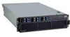
IBM 88643RU Service Guide - Page 111
action
 |
UPC - 000435958211
View all IBM 88643RU manuals
Add to My Manuals
Save this manual to your list of manuals |
Page 111 highlights
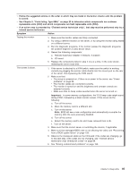
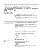
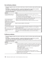
v Follow the suggested actions in the order in which they are listed in the Action column until the problem is solved. v See Chapter 3, "Parts listing, Type 8864," on page 23 to determine which components are customer replaceable units (CRU) and which components are field replaceable units (FRU). v If an action step is preceded by "(Trained service technician only)", that step must be performed only by a trained service technician. Symptom Action Testing the monitor 1. Make sure the monitor cables are firmly connected. 2. Try using a different monitor on the server, or try using the monitor being tested on a different server. 3. Run the diagnostic programs. If the monitor passes the diagnostic programs, the problem might be a video device driver. 4. Reseat the following components: a. Remote Supervisor Adapter II SlimLine, if present b. I/O board 5. Replace the components listed in step 4 one at a time, in the order shown, restarting the server each time. The screen is blank. 1. If the server is attached to a KVM switch, make sure the switch is working correctly by plugging the monitor cable directly into the correct port on the rear of the server, thus bypassing the KVM switch. 2. Make sure that: v The server is powered on. If there is no power to the server, see "Power problems" on page 98. v The monitor cables are connected correctly. v The monitor is turned on and the brightness and contrast controls are adjusted correctly. v Make sure that no beep codes sounded when the server is turned on. Important: In some memory configurations, the 3-3-3 beep code might sound during POST, followed by a blank monitor screen. If this occurs do the following: a. Turn off the server. b. Move the memory card to a different slot. c. Turn on the server. Note: BIOS will see a new configuration and automatically re-enable the memory slots the were previously disabled. d. Turn off the server. e. Return the memory card to the slot it was removed from in 2b. f. Turn on the server. 3. Make sure that the correct server is controlling the monitor, if applicable. 4. Make sure that damaged BIOS code is not affecting the video; see "Recovering from a BIOS update failure" on page 129. 5. Observe the checkpoint LEDs on the I/O board; if the codes are changing, go to the next step. if the codes are not changing, see "(Trained service technicians only) Checkpoint codes" on page 88. 6. See "Solving undetermined problems" on page 156. Chapter 5. Diagnostics 95
-
 1
1 -
2
-
3
-
4
-
5
-
6
-
7
-
8
-
9
-
10
-
11
-
12
-
13
-
14
-
15
-
16
-
17
-
18
-
19
-
20
-
21
-
22
-
23
-
24
-
25
-
26
-
27
-
28
-
29
-
30
-
31
-
32
-
33
-
34
-
35
-
36
-
37
-
38
-
39
-
40
-
41
-
42
-
43
-
44
-
45
-
46
-
47
-
48
-
49
-
50
-
51
-
52
-
53
-
54
-
55
-
56
-
57
-
58
-
59
-
60
-
61
-
62
-
63
-
64
-
65
-
66
-
67
-
68
-
69
-
70
-
71
-
72
-
73
-
74
-
75
-
76
-
77
-
78
-
79
-
80
-
81
-
82
-
83
-
84
-
85
-
86
-
87
-
88
-
89
-
90
-
91
-
92
-
93
-
94
-
95
-
96
-
97
-
98
-
99
-
100
-
101
-
102
-
103
-
104
-
105
-
 106
106 -
 107
107 -
 108
108 -
 109
109 -
 110
110 -
 111
111 -
 112
112 -
 113
113 -
 114
114 -
 115
115 -
 116
116 -
117
-
118
-
119
-
120
-
121
-
122
-
123
-
124
-
125
-
126
-
127
-
128
-
129
-
130
-
131
-
132
-
133
-
134
-
135
-
136
-
137
-
138
-
139
-
140
-
141
-
142
-
143
-
144
-
145
-
146
-
147
-
148
-
149
-
150
-
151
-
152
-
153
-
154
-
155
-
156
-
157
-
158
-
159
-
160
-
161
-
162
-
163
-
164
-
165
-
166
-
167
-
168
-
169
-
170
-
171
-
172
-
173
-
174
-
175
-
176
-
177
-
178
-
179
-
180
-
181
-
182
-
183
-
184
-
185
-
186
-
187
-
188
-
189
-
190
-
191
-
192
 |
 |
