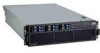
IBM 88643RU Service Guide - Page 117
Universal, Serial, problems, Video, Light, diagnostics
 |
UPC - 000435958211
View all IBM 88643RU manuals
Add to My Manuals
Save this manual to your list of manuals |
Page 117 highlights
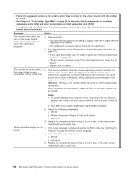
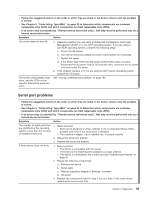
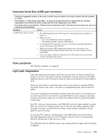
Universal Serial Bus (USB) port problems v Follow the suggested actions in the order in which they are listed in the Action column until the problem is solved. v See Chapter 3, "Parts listing, Type 8864," on page 23 to determine which components are customer replaceable units (CRU) and which components are field replaceable units (FRU). v If an action step is preceded by "(Trained service technician only)", that step must be performed only by a trained service technician. Symptom Action A USB device does not work. 1. Run USB diagnostics (see "Running the on-board diagnostic programs" on page 111). 2. Make sure that: v The correct USB device driver is installed. v The operating system supports USB devices. 3. If a standard PS/2 keyboard or mouse is connected, any USB keyboard or mouse will not work during POST. 4. Make sure that the USB configuration options are set correctly in the Configuration/Setup Utility program menu (see the User's Guide for more information). 5. If you are using a USB hub, disconnect the USB device from the hub and connect it directly to the server. Video problems See "Monitor problems" on page 94. Light path diagnostics Light path diagnostics provides a path that you can follow to help you identify the source of an error. The server must be connected to a power source for the LEDs inside the server to be lit; the server does not have to be turned on for the LEDs to be lit. Press the reset button to reset the server and run the power-on self-test (POST). You might have to use a pen or the end of a straightened paper clip to press the button. The server is designed so that LEDs remain lit when the server is connected to an ac power source but is not turned on, provided that the power supply is operating correctly. This feature helps you to isolate the problem when the operating system is shut down. Any PCI, memory, microprocessor, and VRM LED can be lit again without ac power after you remove the microprocessor tray so that you can isolate a problem. After ac power has been removed from the server, power remains available to these LEDs for up to 24 hours. To view the PCI, memory, microprocessor, and VRM LEDs, press and hold the light-path-diagnostics button on the PCI board, memory card, or microprocessor board for 30 seconds to light the error LEDs. The LEDs that were lit while the server was running will be lit again while the button is pressed. Chapter 5. Diagnostics 101
-
 1
1 -
2
-
3
-
4
-
5
-
6
-
7
-
8
-
9
-
10
-
11
-
12
-
13
-
14
-
15
-
16
-
17
-
18
-
19
-
20
-
21
-
22
-
23
-
24
-
25
-
26
-
27
-
28
-
29
-
30
-
31
-
32
-
33
-
34
-
35
-
36
-
37
-
38
-
39
-
40
-
41
-
42
-
43
-
44
-
45
-
46
-
47
-
48
-
49
-
50
-
51
-
52
-
53
-
54
-
55
-
56
-
57
-
58
-
59
-
60
-
61
-
62
-
63
-
64
-
65
-
66
-
67
-
68
-
69
-
70
-
71
-
72
-
73
-
74
-
75
-
76
-
77
-
78
-
79
-
80
-
81
-
82
-
83
-
84
-
85
-
86
-
87
-
88
-
89
-
90
-
91
-
92
-
93
-
94
-
95
-
96
-
97
-
98
-
99
-
100
-
101
-
102
-
103
-
104
-
105
-
106
-
107
-
108
-
109
-
110
-
111
-
 112
112 -
 113
113 -
 114
114 -
 115
115 -
 116
116 -
 117
117 -
 118
118 -
 119
119 -
 120
120 -
 121
121 -
 122
122 -
123
-
124
-
125
-
126
-
127
-
128
-
129
-
130
-
131
-
132
-
133
-
134
-
135
-
136
-
137
-
138
-
139
-
140
-
141
-
142
-
143
-
144
-
145
-
146
-
147
-
148
-
149
-
150
-
151
-
152
-
153
-
154
-
155
-
156
-
157
-
158
-
159
-
160
-
161
-
162
-
163
-
164
-
165
-
166
-
167
-
168
-
169
-
170
-
171
-
172
-
173
-
174
-
175
-
176
-
177
-
178
-
179
-
180
-
181
-
182
-
183
-
184
-
185
-
186
-
187
-
188
-
189
-
190
-
191
-
192
 |
 |
