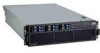
IBM 88643RU Service Guide - Page 119
illustration
 |
UPC - 000435958211
View all IBM 88643RU manuals
Add to My Manuals
Save this manual to your list of manuals |
Page 119 highlights
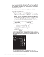
diagnostics panel. This information and the information in "Light path diagnostic LEDs" on page 104 can often provide enough information to correct the error. 3. Remove the server cover and look inside the server for lit LEDs. Certain components inside the server have LEDs that will be lit to indicate the location of a problem. For example, a VRM error will light the LED next to the failing VRM on the microprocessor tray. The following illustration shows the LEDs and connectors on the microprocessor tray. Light path diagnostics button Fan 6 Fan 2 Memory card 1 Memory card 2 Memory card 3 Fan 3 Fan 8 Fan 7 Fan 5 Memory card 4 Fan 1 Microprocessor card error LED Fan 4 Microprocessor 1 socket 1 2 4 3 Microprocessor 3 VRM connector Microprocessor 4 VRM connector Microprocessor 2 socket Microprocessor 1 error LED Microprocessor 2 error LED VRM 4 error LED VRM 3 error LED Microprocessor 3 error LED Microprocessor 3 socket Microprocessor 4 error LED Microprocessor 4 socket The following illustration shows the LEDs on the PCI board. PCI attention LEDs PCI power LEDs Power good LED Chapter 5. Diagnostics 103
-
 1
1 -
2
-
3
-
4
-
5
-
6
-
7
-
8
-
9
-
10
-
11
-
12
-
13
-
14
-
15
-
16
-
17
-
18
-
19
-
20
-
21
-
22
-
23
-
24
-
25
-
26
-
27
-
28
-
29
-
30
-
31
-
32
-
33
-
34
-
35
-
36
-
37
-
38
-
39
-
40
-
41
-
42
-
43
-
44
-
45
-
46
-
47
-
48
-
49
-
50
-
51
-
52
-
53
-
54
-
55
-
56
-
57
-
58
-
59
-
60
-
61
-
62
-
63
-
64
-
65
-
66
-
67
-
68
-
69
-
70
-
71
-
72
-
73
-
74
-
75
-
76
-
77
-
78
-
79
-
80
-
81
-
82
-
83
-
84
-
85
-
86
-
87
-
88
-
89
-
90
-
91
-
92
-
93
-
94
-
95
-
96
-
97
-
98
-
99
-
100
-
101
-
102
-
103
-
104
-
105
-
106
-
107
-
108
-
109
-
110
-
111
-
112
-
113
-
 114
114 -
 115
115 -
 116
116 -
 117
117 -
 118
118 -
 119
119 -
 120
120 -
 121
121 -
 122
122 -
 123
123 -
 124
124 -
125
-
126
-
127
-
128
-
129
-
130
-
131
-
132
-
133
-
134
-
135
-
136
-
137
-
138
-
139
-
140
-
141
-
142
-
143
-
144
-
145
-
146
-
147
-
148
-
149
-
150
-
151
-
152
-
153
-
154
-
155
-
156
-
157
-
158
-
159
-
160
-
161
-
162
-
163
-
164
-
165
-
166
-
167
-
168
-
169
-
170
-
171
-
172
-
173
-
174
-
175
-
176
-
177
-
178
-
179
-
180
-
181
-
182
-
183
-
184
-
185
-
186
-
187
-
188
-
189
-
190
-
191
-
192
 |
 |
