IBM 88643RU Service Guide - Page 22
Power-supply, connector, Video, Ethernet, activity, System, serial, Serial, Mouse, Keyboard, Remote
 |
UPC - 000435958211
View all IBM 88643RU manuals
Add to My Manuals
Save this manual to your list of manuals |
Page 22 highlights
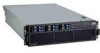
Rear view The following illustration shows the connectors and LEDs on the rear of the server. Power-supply connector: Connect the power cord to this connector. Video connector: Connect a monitor to this connector. USB 1 connector: Connect a USB device to this connector. SP Ethernet 10/100 connector: Use this connector to connect the service processor to a network. SP Ethernet 10/100 activity LED: This LED is on the SP Ethernet 10/100 connector. When this LED is lit, it indicates that there is activity between the server and the network. SP Ethernet 10/100 link LED: This LED is on the SP Ethernet 10/100 connector. When this LED is lit, it indicates that there is an active connection on the Ethernet port. USB 2 connector: Connect a USB device to this connector. System serial connector: Connect a 9-pin serial device to this connector. SP Serial connector: Connect a 9-pin serial device to this connector. Mouse connector: Connect a mouse or other device to this connector. Keyboard connector: Connect a keyboard to this connector. Remote Supervisor Adapter II SlimLine status LED: This LED is on the I/O board and is visible on the rear of the server. When this LED flashes, it indicates that there is activity on the Remote Supervisor Adapter II SlimLine. When this LED is lit continuously, it indicates that there is a problem with the Remote Supervisor Adapter II SlimLine. 6 IBM System x3850 Type 8864: Problem Determination and Service Guide
-
 1
1 -
2
-
3
-
4
-
5
-
6
-
7
-
8
-
9
-
10
-
11
-
12
-
13
-
14
-
15
-
16
-
 17
17 -
 18
18 -
 19
19 -
 20
20 -
 21
21 -
 22
22 -
 23
23 -
 24
24 -
 25
25 -
 26
26 -
 27
27 -
28
-
29
-
30
-
31
-
32
-
33
-
34
-
35
-
36
-
37
-
38
-
39
-
40
-
41
-
42
-
43
-
44
-
45
-
46
-
47
-
48
-
49
-
50
-
51
-
52
-
53
-
54
-
55
-
56
-
57
-
58
-
59
-
60
-
61
-
62
-
63
-
64
-
65
-
66
-
67
-
68
-
69
-
70
-
71
-
72
-
73
-
74
-
75
-
76
-
77
-
78
-
79
-
80
-
81
-
82
-
83
-
84
-
85
-
86
-
87
-
88
-
89
-
90
-
91
-
92
-
93
-
94
-
95
-
96
-
97
-
98
-
99
-
100
-
101
-
102
-
103
-
104
-
105
-
106
-
107
-
108
-
109
-
110
-
111
-
112
-
113
-
114
-
115
-
116
-
117
-
118
-
119
-
120
-
121
-
122
-
123
-
124
-
125
-
126
-
127
-
128
-
129
-
130
-
131
-
132
-
133
-
134
-
135
-
136
-
137
-
138
-
139
-
140
-
141
-
142
-
143
-
144
-
145
-
146
-
147
-
148
-
149
-
150
-
151
-
152
-
153
-
154
-
155
-
156
-
157
-
158
-
159
-
160
-
161
-
162
-
163
-
164
-
165
-
166
-
167
-
168
-
169
-
170
-
171
-
172
-
173
-
174
-
175
-
176
-
177
-
178
-
179
-
180
-
181
-
182
-
183
-
184
-
185
-
186
-
187
-
188
-
189
-
190
-
191
-
192
 |
 |
