IBM HS22 User Guide - Page 43
Installing a memory module, Save Settings, Independent channel mode - blade memory configuration
 |
UPC - 883436054232
View all IBM HS22 manuals
Add to My Manuals
Save this manual to your list of manuals |
Page 43 highlights
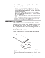
Installing a memory module Use these instructions to install memory modules in the blade server. The blade server has a total of twelve direct inline memory module (DIMM) slots. The blade server supports very low profile (VLP) DDR3 DIMMs with error code correction (ECC) in 1 GB, 2 GB, 4 GB, 8 GB, and 16 GB capacities. For a current list of supported DIMMs for the blade server, see http://www.ibm.com/servers/ eserver/serverproven/compat/us/. After you install or remove a DIMM, you must change and save the new configuration information by using the Setup utility. When you turn on the blade server, a message indicates that the memory configuration has changed. Start the Setup utility and select Save Settings (see "Setup utility menu" on page 60 for more information) to save changes. The memory is accessed internally through the system using six channels. Each channel contains two DIMM connectors. The following table lists each channel and which DIMM connectors belong to the channel. Table 2. Memory channel configuration Memory channel Channel 0 Channel 1 Channel 2 Channel 3 Channel 4 Channel 5 DIMM connector DIMM connector 1 and 2 DIMM connector 5 and 6 DIMM connector 3 and 4 DIMM connector 7 and 8 DIMM connector 11 and 12 DIMM connector 9 and 10 Depending on the memory mode that is set in the Setup utility, the blade server can support a minimum of 1 GB and a maximum of 48 GB of system memory on the system board in a blade server with one processor. If two microprocessors are installed, the blade server can support a minimum of 2 GB and a maximum of 96 GB of system memory. There are two different memory modes: v Independent channel mode: Independent channel mode gives a maximum of 96 GB of usable memory with one CPU installed, and 192 GB of usable memory with 2 CPUs installed (using 16 GB DIMMs). The DIMMs can be installed without matching sizes. See the table below for the memory installation order. Table 3. System memory configuration for independent channel mode (1 microprocessor) Installed DIMM socket memory 1 2 3 4 5 6 7 8 9 10 11 12 1 DIMM X 2 DIMMs X X 3 DIMMs X X X 4 DIMMs X X X X 5 DIMMs X X X X X 6 DIMMs X X X X X X Chapter 3. Installing options 29
-
 1
1 -
2
-
3
-
4
-
5
-
6
-
7
-
8
-
9
-
10
-
11
-
12
-
13
-
14
-
15
-
16
-
17
-
18
-
19
-
20
-
21
-
22
-
23
-
24
-
25
-
26
-
27
-
28
-
29
-
30
-
31
-
32
-
33
-
34
-
35
-
36
-
37
-
 38
38 -
 39
39 -
 40
40 -
 41
41 -
 42
42 -
 43
43 -
 44
44 -
 45
45 -
 46
46 -
 47
47 -
 48
48 -
49
-
50
-
51
-
52
-
53
-
54
-
55
-
56
-
57
-
58
-
59
-
60
-
61
-
62
-
63
-
64
-
65
-
66
-
67
-
68
-
69
-
70
-
71
-
72
-
73
-
74
-
75
-
76
-
77
-
78
-
79
-
80
-
81
-
82
-
83
-
84
-
85
-
86
-
87
-
88
-
89
-
90
-
91
-
92
-
93
-
94
-
95
-
96
-
97
-
98
-
99
-
100
-
101
-
102
-
103
-
104
-
105
-
106
-
107
-
108
-
109
-
110
 |
 |
