Icom VE-PG4 Installation Guide ver.1.34 - Page 12
Rear panel, LAN] PORT, WAN/LAN] PORT
 |
View all Icom VE-PG4 manuals
Add to My Manuals
Save this manual to your list of manuals |
Page 12 highlights
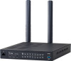
1 Before using the VE-PG4 Panel description ■■Rear panel 1 2 3 1 A1~A4 B1~B4 C1~C4 A1~A4 B1~B4 C1~C4 A1~A4 B1~B4 C1~C4 A1~A4 B1~B4 C1~C4 8 7 6 5 4 1 [ANT1]/[ANT2] CONNECTORS 2 [LAN] PORT (RJ-45 type Attach antennas to communicate with IP transceivers through the 4G/3G line. Always attach two antennas. (p.1-14) [ANT1] is also used for the GPS function. Connect a network device such as a Switch. qw Lights: Connected Blinks: Communicating q green:1000BASE-T w orange: 10BASE-T/100BASE-TX 3 [WAN/LAN] PORT (RJ-45 type Connect a proper device, depending on the Line Type setting. (Router Settings > WAN > Connection Type) See the Operating guide for details. ••Used as a LAN port (default) Connect a network device such as a Switch or Router modem. ••DHCP Client, Static IP, or PPPoE Connect a bridge modem (ADSL, VDSL or CATV) or FTTH terminal. Lights: Connected Blinks: Communicating q Green: 1000BASE-T w Orange: 10BASE-T/100BASE-TX qw 4 [GND] TERMINAL 5 [DC] JACK Connect to ground. Connect the supplied power adapter. 1-6
-
 1
1 -
2
-
3
-
4
-
5
-
6
-
 7
7 -
 8
8 -
 9
9 -
 10
10 -
 11
11 -
 12
12 -
 13
13 -
 14
14 -
 15
15 -
 16
16 -
 17
17 -
18
-
19
-
20
-
21
-
22
-
23
-
24
-
25
-
26
-
27
-
28
-
29
-
30
-
31
-
32
-
33
-
34
-
35
-
36
-
37
-
38
-
39
-
40
-
41
-
42
-
43
-
44
-
45
-
46
-
47
-
48
-
49
-
50
-
51
-
52
-
53
-
54
-
55
-
56
-
57
-
58
-
59
-
60
-
61
-
62
-
63
-
64
-
65
-
66
-
67
-
68
-
69
-
70
-
71
-
72
-
73
-
74
-
75
-
76
-
77
-
78
-
79
-
80
-
81
-
82
-
83
-
84
-
85
-
86
-
87
-
88
-
89
-
90
-
91
-
92
-
93
-
94
-
95
-
96
-
97
-
98
-
99
-
100
-
101
-
102
-
103
-
104
-
105
-
106
-
107
-
108
-
109
-
110
-
111
-
112
-
113
-
114
-
115
-
116
-
117
-
118
-
119
-
120
-
121
-
122
-
123
-
124
-
125
-
126
-
127
-
128
-
129
 |
 |
