Icom VE-PG4 Installation Guide ver.1.34 - Page 127
Port details, Pin No., Description
 |
View all Icom VE-PG4 manuals
Add to My Manuals
Save this manual to your list of manuals |
Page 127 highlights
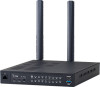
6 For your information Specifications ■■Port details A1~A4 B1~B4 C1~C4 A1~A4 B1~B4 C1~C4 A1~A4 B1~B4 C1~C4 A1~A4 B1~B4 C1~C4 Pin No. A1 A2 A3 A4 B1 B2 B3 B4 C1 C2 C3 C4 Description Analog audio output (From the VE-PG4) / Superimpose PTT Analog GND Analog audio input (To the VE-PG4) / Superimpose squelch detection Analog GND General control output / Single PTT control / Relay output Serial communication (Half duplex) / 8 V power supply / Relay output General control input / Single squelch control Common GND Serial communication TXD (From the VE-PG4) Serial communication RXD (To the VE-PG4) Serial communication RTS (From the VE-PG4) Serial communication CTS (To the VE-PG4) LLYou can change the configuration of ports B1 to B4 on the VE-PG4 setting screen. ••A1/A2 terminal (+/-) Audio output terminal Adjust the output gain according to the audio amplifier that is used. The connected audio equipment may be damaged if the gain is inappropriately set. The length of the cable that connects the audio equipment and VE-PG4 should be less than 10 m (3.3 ft.) Be careful of the noise and malfunction caused by a ground loop. Reference level: Speaker/0 dBs/-20 dBs(0 dBs = 0.775 Vrms) selectable Load impedance: More than 600 Ω (Speaker: 8 Ω) ••A3/A4 terminal (+/-) Audio input terminal Adjust the output gain according to the audio amplifier. When you use a microphone other than an electret condenser microphone (ECM), select "Disable" on the setting screen. Reference level: -10 dBs/-40 dBs(0 dBs=0.775 Vrms) selectable Input impedance: Approximately 10 kΩ (Approximately 1 kΩ when biassed) Supplied voltage: Approximately 2.2 V (For Electret Condenser microphone) ••B1/B2 terminal (+/-) Relay output terminal Turns the connected equipment ON or OFF. ••You can change the configuration of ports B1 to B4 on the VE-PG4 setting screen. (Connection Port Settings > EXT I/O (EXT)) ••Less than 30 V/500 mA. 6-20
-
 1
1 -
2
-
3
-
4
-
5
-
6
-
7
-
8
-
9
-
10
-
11
-
12
-
13
-
14
-
15
-
16
-
17
-
18
-
19
-
20
-
21
-
22
-
23
-
24
-
25
-
26
-
27
-
28
-
29
-
30
-
31
-
32
-
33
-
34
-
35
-
36
-
37
-
38
-
39
-
40
-
41
-
42
-
43
-
44
-
45
-
46
-
47
-
48
-
49
-
50
-
51
-
52
-
53
-
54
-
55
-
56
-
57
-
58
-
59
-
60
-
61
-
62
-
63
-
64
-
65
-
66
-
67
-
68
-
69
-
70
-
71
-
72
-
73
-
74
-
75
-
76
-
77
-
78
-
79
-
80
-
81
-
82
-
83
-
84
-
85
-
86
-
87
-
88
-
89
-
90
-
91
-
92
-
93
-
94
-
95
-
96
-
97
-
98
-
99
-
100
-
101
-
102
-
103
-
104
-
105
-
106
-
107
-
108
-
109
-
110
-
111
-
112
-
113
-
114
-
115
-
116
-
117
-
118
-
119
-
120
-
121
-
 122
122 -
 123
123 -
 124
124 -
 125
125 -
 126
126 -
 127
127 -
 128
128 -
 129
129
 |
 |
