Icom VE-PG4 Installation Guide ver.1.34 - Page 22
Connecting the cables and the PC
 |
View all Icom VE-PG4 manuals
Add to My Manuals
Save this manual to your list of manuals |
Page 22 highlights
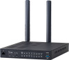
1 Before using the VE-PG4 Installation and connections ■■Connecting the cables and the PC r Verify the indications Check the LAN cable connection if no indicator lights. qw Lights: Connected Blinks: Communicating q green:1000BASE-T w orange: 10BASE-T/100BASE-TX VE-PG4 (Default: 192.168.0.1) e Boot the PC PC (Example: 192.168.0.100) LAN cable* (User supplied) *Category 5e or higher To the [LAN] port q Connect cables T o the To the DC jack Ground terminal w Connect to the power supply The [PWR] indicator on the front panel lights. Power adapter (Supplied) AC outlet Ground terminal Grounding wire (User supplied) NOTE: Use the supplied clamp to fix the power cable to the ground terminal. Power cable Ground terminal Clamp (Supplied) Grounding wire (User supplied) 1-16
-
 1
1 -
2
-
3
-
4
-
5
-
6
-
7
-
8
-
9
-
10
-
11
-
12
-
13
-
14
-
15
-
16
-
 17
17 -
 18
18 -
 19
19 -
 20
20 -
 21
21 -
 22
22 -
 23
23 -
 24
24 -
 25
25 -
 26
26 -
 27
27 -
28
-
29
-
30
-
31
-
32
-
33
-
34
-
35
-
36
-
37
-
38
-
39
-
40
-
41
-
42
-
43
-
44
-
45
-
46
-
47
-
48
-
49
-
50
-
51
-
52
-
53
-
54
-
55
-
56
-
57
-
58
-
59
-
60
-
61
-
62
-
63
-
64
-
65
-
66
-
67
-
68
-
69
-
70
-
71
-
72
-
73
-
74
-
75
-
76
-
77
-
78
-
79
-
80
-
81
-
82
-
83
-
84
-
85
-
86
-
87
-
88
-
89
-
90
-
91
-
92
-
93
-
94
-
95
-
96
-
97
-
98
-
99
-
100
-
101
-
102
-
103
-
104
-
105
-
106
-
107
-
108
-
109
-
110
-
111
-
112
-
113
-
114
-
115
-
116
-
117
-
118
-
119
-
120
-
121
-
122
-
123
-
124
-
125
-
126
-
127
-
128
-
129
 |
 |
