Intel SR2600UR Service Guide - Page 126
Installing the SATA Cables, Replacing a Fan Module on,
 |
UPC - 735858206778
View all Intel SR2600UR manuals
Add to My Manuals
Save this manual to your list of manuals |
Page 126 highlights
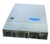
a. Connect the hard drive SATA cables from either the server board or the add-in card to the corresponding SATA connectors on the midplane board. B A0 Air Baffle 0 12 34 5 BoaSrderver 4 5 6 1 7 2 3 MidpPlaansesive AF003071 Figure 99. Installing the SATA Cables b. If you connect the SATA cables from the passive midplane to the add-in card, also install the 3-pin white cable between the HBA connector on the midplane and the add-in card to enable fault LED control. Note: Do NOT connect the HBA cable in a system with an active midplane or when using the SATA connectors on the server board to connect the hard drive SATA cables. 6. Install the fan module. For instructions, see "Replacing a Fan Module" on page 127. 7. Install the bridge board as follows: a. Open the retention clips on both ends (see letter "A" in Figure 100). b. Slide the bridge board through the fan assembly (see letter "B" in Figure 100). c. Insert the bridge board into the bridge board connector on the midplane and server board (see letter "C" in Figure 100). 106 Intel® Server System SR2600UR/SR2625UR Service Guide
-
 1
1 -
2
-
3
-
4
-
5
-
6
-
7
-
8
-
9
-
10
-
11
-
12
-
13
-
14
-
15
-
16
-
17
-
18
-
19
-
20
-
21
-
22
-
23
-
24
-
25
-
26
-
27
-
28
-
29
-
30
-
31
-
32
-
33
-
34
-
35
-
36
-
37
-
38
-
39
-
40
-
41
-
42
-
43
-
44
-
45
-
46
-
47
-
48
-
49
-
50
-
51
-
52
-
53
-
54
-
55
-
56
-
57
-
58
-
59
-
60
-
61
-
62
-
63
-
64
-
65
-
66
-
67
-
68
-
69
-
70
-
71
-
72
-
73
-
74
-
75
-
76
-
77
-
78
-
79
-
80
-
81
-
82
-
83
-
84
-
85
-
86
-
87
-
88
-
89
-
90
-
91
-
92
-
93
-
94
-
95
-
96
-
97
-
98
-
99
-
100
-
101
-
102
-
103
-
104
-
105
-
106
-
107
-
108
-
109
-
110
-
111
-
112
-
113
-
114
-
115
-
116
-
117
-
118
-
119
-
120
-
 121
121 -
 122
122 -
 123
123 -
 124
124 -
 125
125 -
 126
126 -
 127
127 -
 128
128 -
 129
129 -
 130
130 -
 131
131 -
132
-
133
-
134
-
135
-
136
-
137
-
138
-
139
-
140
-
141
-
142
-
143
-
144
-
145
-
146
-
147
-
148
-
149
-
150
-
151
-
152
-
153
-
154
-
155
-
156
-
157
-
158
-
159
-
160
-
161
-
162
-
163
-
164
-
165
-
166
-
167
-
168
-
169
-
170
-
171
-
172
-
173
-
174
-
175
-
176
-
177
-
178
-
179
-
180
-
181
-
182
-
183
-
184
-
185
-
186
-
187
-
188
-
189
-
190
-
191
-
192
-
193
-
194
-
195
-
196
-
197
-
198
-
199
-
200
-
201
-
202
-
203
-
204
-
205
-
206
-
207
-
208
-
209
-
210
-
211
-
212
-
213
-
214
-
215
-
216
-
217
-
218
-
219
-
220
-
221
-
222
-
223
-
224
-
225
-
226
-
227
-
228
-
229
-
230
-
231
-
232
-
233
-
234
 |
 |
